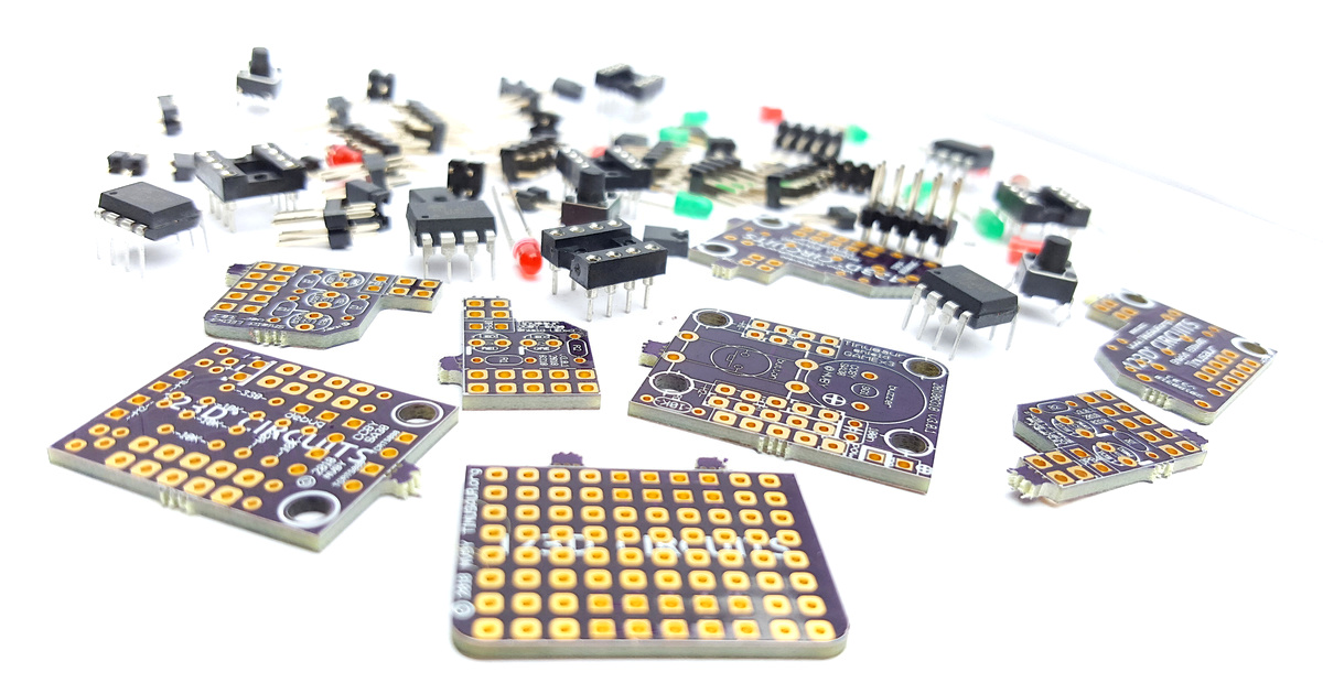
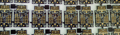
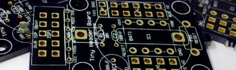
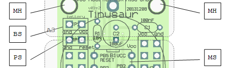
We’re almost at the end of our Indiegogo campaign and as you might be aware there is a delay in the production of the kits.
At TINUSAUR we strive to achieve the higher quality of the products. Unfortunately, while making the PCBs, the most important part of our boards, and working with some new suppliers, we were not happy with the quality of the production. Luckily, the great guys at OSHPARK jumped in and helped us get the PCB we need at the cost we could afford to keep the price points of our product low and affordable.
Good news – all the PCBs arrived a few days ago. We’ve assembled few pieces of them to make sure everything is fine and, with the exception of few minor glitches, all is good and ready to go.
This week we are packaging the broads and the components.
Next week we will start shipping the first batches of kits to the supporters.
This shield is an upgrade from the previous Tinusaur Starter where we had to solder the LED and the resistor to a tiny 2-pin male header. With the shield is so much easier and fun.
This a short guide about how to assemble the Tinusaur Board.
Tinusaur Board
The Tinusaur Board is what the Tinusaur project is built around. It is rather simple PCB with a dozen components on it.
The board is easy to assemble and does not require very special skills or instruments.
IMPORTANT: If you are uncertain about anything please consult with our website, community or someone more knowledgeable in the subject.
There are 4 areas that the Tinusaur board could be divided to: A1, A2, A3, A4.
Assembling
Here is the recommended order of soldering the parts:
MCU socket. Note: do not insert the chip yet.
Capacitors C1, C2 and resistor R1.
Headers H1, H2.
External power header – red.
Battery on/off header – yellow.
ISP header.
Battery holder.
RESET button.
The battery holder and the battery are optional but if you decided to put them on make sure you solder the battery holder before the RESET button.
IMPORTANT:
External power header (JP1, red, the one closer to the 8-pin header H1) is to connect external power. DO NOT put a jumper there – that could damage the board.
Battery On/Of header (JP2, yellow, the one closer to the mount hole) is to connect/disconnect battery to/from the board. DO NOT have this on while the board is connected to the programmer or external power source – there is no circuit to protect the battery from overcharging.
If you’re not going to use an external power source or the battery on the board don’t put any jumper on at all.
Board Components
Name
Description
PCB
Tinusaur Board
MCU, Attiny85
Atmel AVR ATtiny85 microcontroller
Socket, DIP-8
DIP-8 socket for MCU
H1, Header
Header 2×4, Female
H2, Header
Header 2×5, Female
ISP, Header
Header 2×5, Male, for ISP
RESET, Button
Tactile push button, for RESET
Power, Header
Header 1×2, Male, red – external power
Battery, Header
Header 1×2, Male, yellow – battery power on/off
Battery, Jumper
Jumper, 2-pin, yellow – for battery power on/off
C1, Capacitor
Capacitor 100uF, Low profile 5×5 mm
C2, Capacitor
Capacitor 100nF, Small
R1, Resistor
Resistor 10K, Small, 1/8W
Battery holder
Battery holder for CR2032
Battery 3V
Battery 3V, CR2032
Note (about external power source): If you’re going to use external power source (JP1, red in color, the one close to the 8-pin header H1) make sure you connect the negative pole (-) to the outer pin of the header and positive (+) to the inner one.
Note (about battery placement): If you’re going to use the battery in the holder make sure you insert it correctly – that is to have the negative (-) downwards (facing the holder) and the positive (+) (the side with the text markings) upwards.
This guide as well as other documents are available as PDF at the Guides page. Please note that any updates will be posted there.
Some of the people who received the Tinusaur Starter kit wrote us that it isn’t that easy to figure and remember how to put and use the 2 small 2×1 headers for the external power and the battery on/off. So, we decided to make a small change – have those in different colors.
PS1 (external power source) is now red.
BS1, BJ1 (battery switch and jumper) are now yellow.
Even though the Tinusaur is a very simple thing it has its advantages as well as disadvantages that need to be addressed.
It is a platform that is simple and easy to understand for everyone – perfect for a quick start and in learning how to create things.
The board consists of the minimum required components for its micro-controller to function properly. There are no missing parts that could save on space and cost but may impact stability. There are no extra components that you may not always need.
There are benefits of choosing the Tinusaur over some other similar projects.
There are of course things that are not perfect with the Tinusaur and we must mention them a.
Still interested …
More details are laid out in the Pros and Cons page.
Dear friends, I’m glad to inform you that all the parts and the boards finally arrived.
So we’re ready to offer the Starter Kit to those that are interested.
Boards were produced by OSHPark – they look great, as usual.
We also received a small batch from SeeedStudio – cheaper but still looks good.
We are now preparing the purchasing option – a PayPal button or may something more complex – we haven’t decided yet. There is this “Start your own online store front” list of options that we consider looking at. Any feedback or shared experience we will appreciate very much.
Initially, we will put up for sale a very small batch – 20 or so packages – we don’t know what the interest will be, but we have the capacity to ship about 80 more.
We have a shield-like proto board now, very preliminary design. It will allow you to solder some components on it and then put it on top of the Tinusaur Board – very much like any other shield-like board. It is available on OSHPark at this address: https://oshpark.com/shared_projects/2zuAJJGZ.
All the parts for the Tinusaur Starter kit were ordered from our suppliers. We hope everything to be in our office (most of them already arrived) by the end of the month. Will post more information about it here and on our Twitter/Facebook/etc.
The boards for the Tinusaur Starter were ordered from OSHPark – great quality, no doubt. We also ordered some boards from Seeed Studio to see how’s their quality.
As follow up to our first Tutorial 001 we are planing to put another one – Tutorial 002, probably about how to connect a push-button to the board and receive input from it.
In this post are discussed some of principals used while designing this board.
Size and form factor
The goal of making this board is not to have a smaller or the smallest PCB that runs on ATtiny. The goal is to have a board that could be used for prototyping simple projects as well as fitting reasonable small (or large, depending on the view) circuits on an additional shield board.
Headers
There are 2 header – one 2×4 – H1 and another one 2×5 – H2.
The idea is that all the outer pins are GND while all the inner pins are connected directly to the MCU. The longer header H2 has its top-left pin connected to the Vcc like the 2nd-row one on the left. That gives us one more power source wire.
MCU
This board could work with the smaller Atmel AVR ATtiny controllers such as ATtiny 25/45/85, ATtiny13 as well as most of their variations – as long as they are in DIP-8 case.
Programming
The programming is done through the standard 10-pin ISP connector using any compatible AVR ISP programmer. On the diagram below it is marked as PC.
The connector is placed on the board in such a way so it could be chopped off if not needed and make the board little smaller. The programming probe, marked as PP on the diagram below, has holes that could help in the cutting. In case you need to connect the board to a programmer again at later time you can solder some wires to what’s left of the probe.
Board
Technical parameters: 2 layer board of 0.90×1.40 inches (22.96×35.66 mm).
There are 4 mounting holes marked as MH on the diagram below.
Power
During the development the board could be powered through the ISP programmer.
External power source could be connected to the board through a jumper marked as PS on the diagram below.
There is an optional button-cell battery mount on the back of the board, marked as BM on the diagram below. The battery could be switched on and off using the jumper that is marked as BS on the diagram.
Areas
There are 4 areas that a Tinusaur board could be divided to: A1, A2, A3, A4. That is applicable for the actual Tinusaur main board as well as any shield boards one could produce.
A1, the bottom part of the board:
this is the area where the RESET button is placed on the main board.
for a shield board that area could be used to put some components and produce a simple circuit.
A2, the mid of the board – heads:
there are 2 header – one 2×4 and another one 2×5, they are different for a reason.
on the main board, between the headers, is placed the MCU.
on a shield board, between the headers, could placed a 8-pin chip or other components.
A3, the top part of the board:
there are the minimum required components for the MSU to work – 2 capacitors for the power source and one pull-up resistor for the RESET.