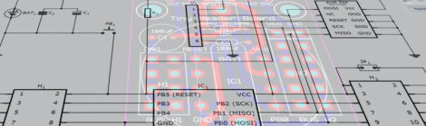
The new prototype PCBs just arrived from OSHPark
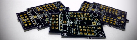
The new prototype PCBs just arrived from OSHPark – great quality as usual. I noticed that there are only few things that I may change before call it official: slightly move some components around so they fit better and become easier to solder; add one jumper for switch on/off the optional button cell battery on … Read more