Another two-day workshop about microcontrollers, soldering and Tinusaur

Another two-day workshop about microcontrollers, soldering and Tinusaur

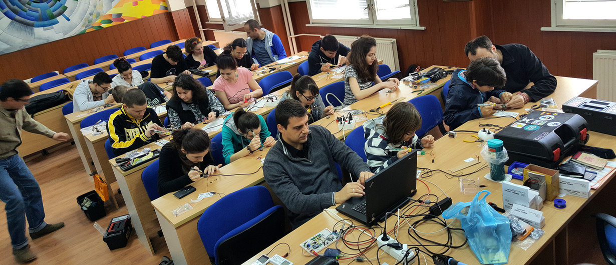
There was another “Microcontrollers, soldering and Tinusaurworkshop in our town of Veliko Tarnovo, a few days ago.

On the first day, we assembled some boards, the second day we wrote some programs.

For the younger kids, there were much simpler things to do – soldering blinking LED with 2 transistors, a few other components, and a battery.

Day 1

Just assembling various boards.

Tinusaur Board

This is the Tinusaur Board from the Tinusaur Starter 2 kit.

Tinusaur Board Parts

It wasn’t difficult for anyone to do that. There are markings on the PCB that tell you where to put each component and in what direction.

The only important thing to know is that you solder the RESET button last, before that you solder the battery socket on the bottom side of the PCB.

Tinusaur Shield LEDx2

This is the Shield LEDx2 from the Tinusaur Starter 2 kit.

Tinusaur Shield LEDx2 Parts

This shield is an upgrade from the previous Tinusaur Starter where we had to solder the LED and the resistor to a tiny 2-pin male header. With the shield is so much easier and fun.

LED Matrix 8×8 with MAX7219 Controller

This is a LED matrix 8×8 with a MAX7219 controller.

LED Matrix 8x8 MAX7219 Controller

That was something new. They sell on eBay at a very affordable prices: http://www.ebay.com/itm/191736585164

Even while we’re soldering it people were coming with ideas about what we could do with it.

Day 2

The second day was dedicated to programming what we’ve assembled the previous day.

Software and Arduino IDE Setup

That’s how we started day 2.

A short guide about how to setup the Arduino IDE to work with the Tinusaur boards is available at the Arduino IDE Setup page.

Blinking LED

The “Hello, World!” in the microcontrollers’ world.

Source code available at https://bitbucket.org/tinusaur/tutorials/src/default/tut004a_blinking_leds/.

A separate blog post and tutorial page will be available soon.

LED Matrix 8×8

The biggest challenge here was to make the MAX7219LED8x8 library work in the Arduino IDE environment.

We’ll do another post about that in the next few days.

UPDATE 2022: The MAX7219LED8x8 library, now renamed to MAX7219tiny has now a new home at tinusaur.com/libraries/max7219tiny. Check also this MAX7219 & ATtiny85 tutorial to learn how the library works.

The First Tinusaur Workshop

The first official Tinusaur workshop took place last Sunday (on the 14th of December) in the Veliko Turnovo University “St. St. Cyril and Methodius”. It was really great!

The workshop was attended by 22 people of age 16 to 44.

The Tinusaur Workshop

As you may have guessed already it was for the absolute beginners so we first learned how to solder basic things like resistors, capacitors and other small parts. Then we move to soldering The Tinusair Board.

The second part was programming the with the “Hello World” of the microcontrollers – a blinking LED.

Not all people who wanted could attend the even so we may organize another one in the first months of the next year.


TinuDHT – ATtiny Library for DHT11

Ever wanted to do a project with that cheap DHT11 temperature/humidity sensor and did not want to go the Arduino way but with a simple ATtiny85? You probably know already about  the issues with the existing Arduino based libraries running on the ATtiny microcontrollers, but can’t deal with them. TinuDHT is our answer to this.

TinuDHT is a C library for working with the DHT11 temperature/humidity sensor intended to be used with the Tinusaur but should also work with any other board based on ATtiny85 or similar microcontroller.

DHT11

The DHT11 is very basic, low-cost digital temperature and humidity sensor. It uses a capacitive humidity sensor and a thermistor for measurements, and sends out the info to the data pin. It is relatively simple to use it, but requires precise timing to retrieve the data correctly. One disadvantage of this sensor is that you can get new data from it no more often than once every 1 or 2 seconds.

The primary problem with the direct use of the Arduino libraries is that the ATtiny85 and Tinusaur in particular do not have enough resource to handle the send/receive process properly, i.e. not enough CPU power, in result of which the timing of the signals that are sent to the sensor and received from it become messed up. In addition those libraries use Arduino specific code and/or C++ specific syntax which makes them incompatible with the plain C language.

TinuDHT library is based on DHT11Lib code. It was adapted for ATtiny, removed Arduino dependencies and timing was adjusted to work well on ATtiny85 at 1 MHz. There are few other changes and optimizations for speed and size.

TinuDHT is written in plain C and does not require any additional libraries to function except those that come with the WinAVR SDK. Check our WINAVR Setup guide.

Please go to TinuDHT page to see the full document.

The source code of the TinuDHT library is available at https://bitbucket.org/tinusaur/tinudht.

Tinusaur Board DHT11 LCD Battery

Tutorial 002: Fading LED x1

Another beginners tutorial is on the way – this time about a fading in and out LED.

This is simple tutorial that shows how to connect a LED to the ATtiny85 based Tinusaur board and write a program that makes the LED to fade in and out using PWM (pulse-width-modulation) technique.

PWM Diagram

Note: The code in this tutorial does not use the built-in PWM capabilities of the ATtiny microcontrollers, instead it uses direct bit manipulation since this an easier way to understand how it works. Another tutorial should cover the PWM functionality that is built into the microcontroller.

Tinusaur Board with LED

The Tinusaur board is a standard ATtiny breakout board so this could be applied to almost any other board that has ATtiny microcontroller on it. The code was tested to work with ATtiny13, ATtiny25, ATtiny45 and ATtiny85 but will probably work on any other ATtiny microcontrollers as well.

Please go to Tutorial 002: Fading LED x1 to see the full document.

You can also check the Tinusaur Board – Assembling Guide and the WinAVR – Setup Guide.

(UPDATED) Tutorial 001: Blinking LED

Tinusaur Tutorial 001 schematics

Our first tutorial Tutorial 001: Blinking LED (that’s the older one) was just updated and put under the Tutorials menu.

This is very simple tutorial that shows how to connect a LED to the Tinusaur board and write the “Hello World” of the microcontrollers – very simple program that makes a LED to blink.

Since the Tinusaur board is a very standard ATtiny breakout board this could be applied to almost any other board that has ATtiny microcontroller.

The code was tested to work with ATtiny13, ATtiny25, ATtiny45 and ATtiny85 but will probably work with other microcontrollers too.

Please go to the Tutorial 001: Blinking LED x1 page to see the full document.