This is an EXPERIMENTAL VIDEO about how to assemble the Tinusaur Board and learn how to solder.
A better version will be available very soon.
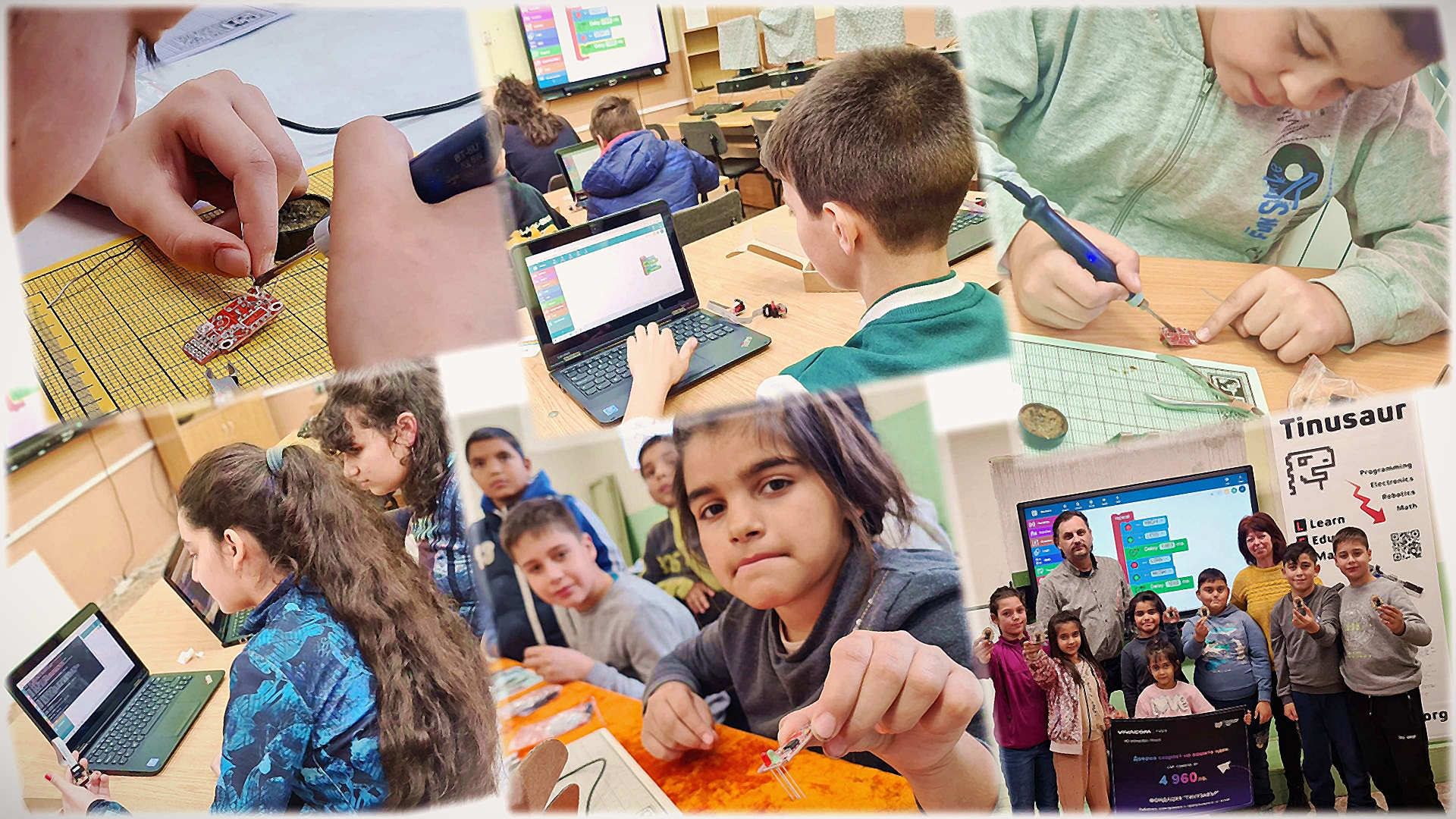
At the end of May 2023, the last of the series of free-of-charge electronics and programming workshops organized by the Tinusaur Foundation as part of the Vivacom Regional Grant project was held. It’s time for a reckoning for our joint project with Vivacom Regional Grant. 8 small schools in the municipality of Veliko Tarnovo, Bulgaria, … Read more
This is an EXPERIMENTAL VIDEO about how to assemble the Tinusaur Board and learn how to solder.
A better version will be available very soon.
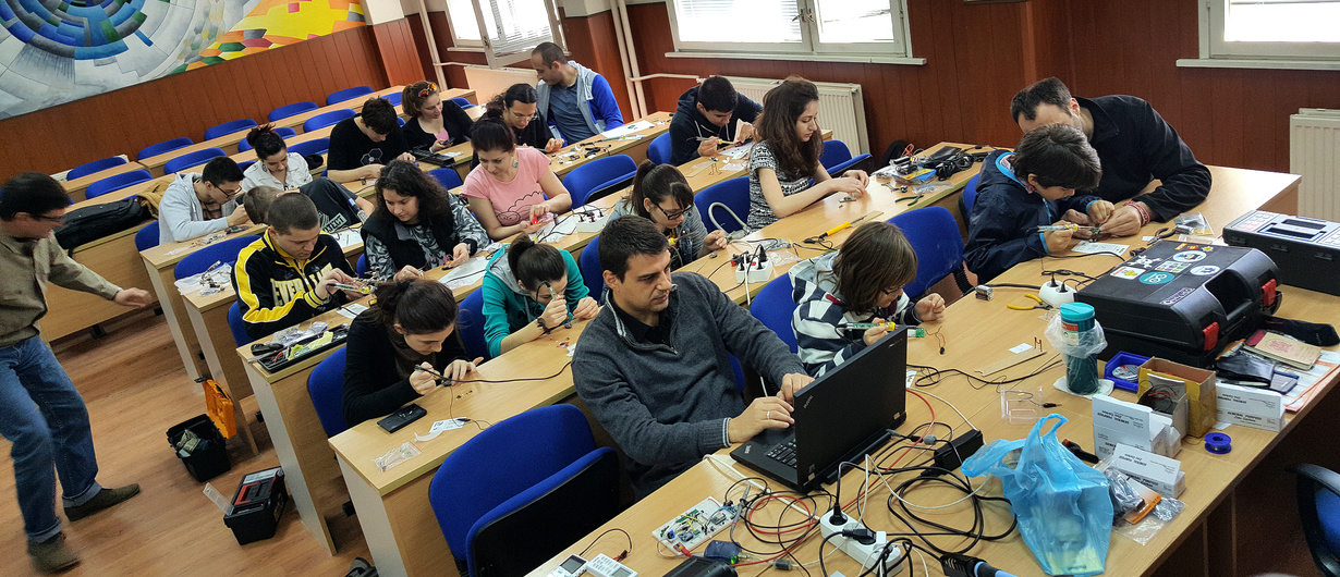
There was another “Microcontrollers, soldering and Tinusaur” workshop in our town of Veliko Tarnovo, a few days ago. On the first day, we assembled some boards, the second day we wrote some programs. For the younger kids, there were much simpler things to do – soldering blinking LED with 2 transistors, a few other components, and … Read more
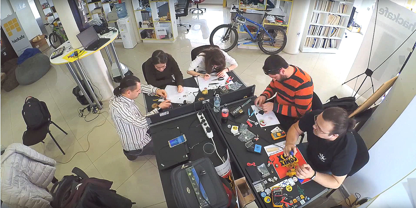
Our first workshop for this year took place couple of weeks ago in Plovdiv at Hackafe. It was part of a much larger event about microcontrollers, robotics and internet-of-things. This time, it was for 2 days and in 3 parts. Part 1 (day 1) was an introduction to the microcontrollers for everyone that was just … Read more
The first official Tinusaur workshop took place last Sunday (on the 14th of December) in the Veliko Turnovo University “St. St. Cyril and Methodius”. It was really great! The workshop was attended by 22 people of age 16 to 44. As you may have guessed already it was for the absolute beginners so we first learned how to … Read more
This a short guide about how to assemble the Tinusaur Board. Tinusaur Board The Tinusaur Board is what the Tinusaur project is built around. It is rather simple PCB with a dozen components on it. The board is easy to assemble and does not require very special skills or instruments. IMPORTANT: If you are uncertain … Read more