How to Setup the Arduino IDE to Work with the Tinusaur Boards

Arduino IDE for Tinusaur Boards

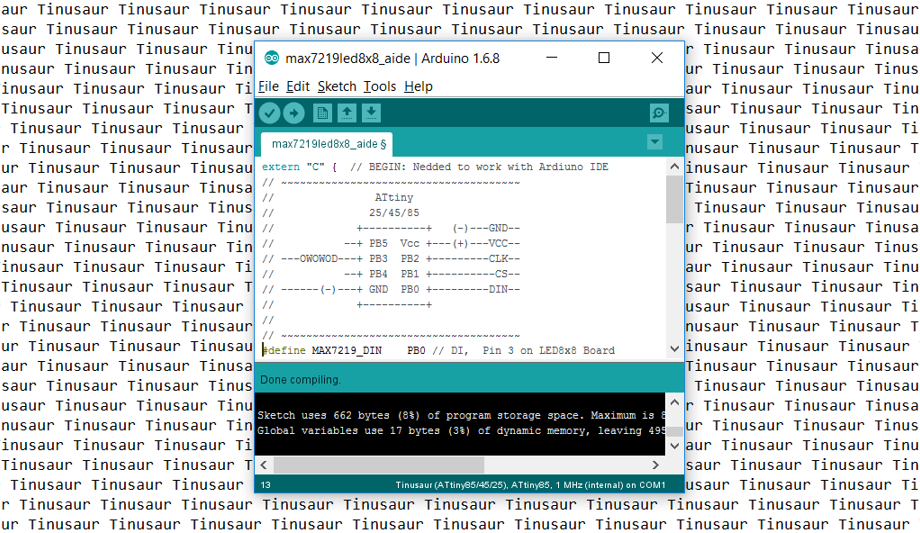
UPDATE: There is an updated version of the Arduino Setup Guide at our new website https://tinusaur.com/guides/arduino-ide-tinusaur-setup/

This is a short guide how to setup the Arduino IDE to work with the Tinusaur boards.

What it does basically is to make it work with the Atmel ATtiny85/45/25 microcontrollers. The only difference is that it will appear on the list of boards as Tinusaur – this is done for convenience, so relatively inexperienced people won’t get confused by the long list of unknown boards and microcontrollers.

Installing the Arduino IDE

First of all, we need the Arduino IDE itself. It could be downloaded from https://www.arduino.cc/en/Main/Software – the official Arduino website. The current version at the time of writing this guide was 1.6.8 but should work with all the most recent versions.

Start the Arduino IDE first.


Adding Support for the Tinusaur Boards

Go to the menu File / Preferences.

Find the “Additional Boards manager URLs” and the button on the right that will open an edit box.

Put the following URL in the edit box:

https://bitbucket.org/tinusaur/arduino-ide-boards/raw/default/package_tinusaur_attiny_index.json

NOTE: It is possible to have multiple URLs as long as they are put on separate lines.

Close the edit dialog by pressing “OK”. Close the “Preferences” dialog by pressing “OK”.

Go to the menu Tools / Board:… / Boards Manager.

This will open an additional dialog window with boards information.

You may need to wait until all data is loaded.

From the drop-down menu “Type” choose the “Contributed” item.

Locate the “Tinusaur Boards” item and click on it.

Press the “Install” button. That will install the necessary files into the Arduino IDE.

Close the dialog by pressing the “Close” button.

Setup to use the Tinusaur Board

Go to menu Tools / Board:…

The Tinusaur should be available somewhere at the bottom of the list. Choose the Tinusaur.

It is important to setup the other parameters for the board.

Go to menu Tools / Processor:… and choose the appropriate CPU type. If unsure choose ATtiny85.

Go to menu Tools / Clock:… and choose the appropriate CPU frequency. If unsure choose 1 MHz.

Go to menu Tools / Programmer:… and choose the appropriate programmer. If unsure choose USBasp.

That’s it.

Another version of this guide but with screenshots is available at the Arduino IDE Setup page.

C Library for ATtiny85 to Work with SSD1306 Controlled OLED Display

UPDATE: Please check the most recent post about this library at /tag/ssd1306xled

I recently bought an OLED display 128×64 from eBay (http://www.ebay.com/sch/i.html?_nkw=OLED+128) – very inexpensive (about 4 euro) but when I finally received it I was surprised to see how small it was – I was expecting something that looked more like the Nokia 3310 LCD. So I thought – this is perfect for the Tinusaur Project. The 128×64 OLED is controlled by an SSD1306 circuit and could be interfaced over I²C. The first challenge that I faced was that all existing libraries that I found were for Arduino boards … and I wrote my own based, of course, on existing code – the SSD1306xLED library.

SSD1306xLED library for OLED/PLED 128x64

SSD1306xLED is a C library for working with the SSD1306 display driver to control dot matrix OLED/PLED 128×64 displays. It is intended to be used with the Tinusaur board but should also work with any other board based on ATtiny85 or similar microcontroller – ATtiny45/ATtiny25, even ATtiny13.

The code could be divided into 3 pieces: (1) communication over I²C with the SSD1306; (2) sending graphical commands to the display; (3) high-level functions such as printing characters.

The I²C communication part is based on modified IIC_wtihout_ACK library that is available on the Internet but its original website (http://www.14blog.com/archives/1358) is no longer functional. Basically, it made it work on ATtiny85 and Tinusaur.

The SSD1306xLED library still needs work and improvements.

The main location for the library is SSD1306xLED page.

The source code along with very simple example is available on Bitbucket at this address: https://bitbucket.org/tinusaur/ssd1306xled


TinuDHT – ATtiny Library for DHT11

Ever wanted to do a project with that cheap DHT11 temperature/humidity sensor and did not want to go the Arduino way but with a simple ATtiny85? You probably know already about  the issues with the existing Arduino based libraries running on the ATtiny microcontrollers, but can’t deal with them. TinuDHT is our answer to this.

TinuDHT is a C library for working with the DHT11 temperature/humidity sensor intended to be used with the Tinusaur but should also work with any other board based on ATtiny85 or similar microcontroller.

DHT11

The DHT11 is very basic, low-cost digital temperature and humidity sensor. It uses a capacitive humidity sensor and a thermistor for measurements, and sends out the info to the data pin. It is relatively simple to use it, but requires precise timing to retrieve the data correctly. One disadvantage of this sensor is that you can get new data from it no more often than once every 1 or 2 seconds.

The primary problem with the direct use of the Arduino libraries is that the ATtiny85 and Tinusaur in particular do not have enough resource to handle the send/receive process properly, i.e. not enough CPU power, in result of which the timing of the signals that are sent to the sensor and received from it become messed up. In addition those libraries use Arduino specific code and/or C++ specific syntax which makes them incompatible with the plain C language.

TinuDHT library is based on DHT11Lib code. It was adapted for ATtiny, removed Arduino dependencies and timing was adjusted to work well on ATtiny85 at 1 MHz. There are few other changes and optimizations for speed and size.

TinuDHT is written in plain C and does not require any additional libraries to function except those that come with the WinAVR SDK. Check our WINAVR Setup guide.

Please go to TinuDHT page to see the full document.

The source code of the TinuDHT library is available at https://bitbucket.org/tinusaur/tinudht.

Tinusaur Board DHT11 LCD Battery

Tutorial 002: Fading LED x1

Another beginners tutorial is on the way – this time about a fading in and out LED.

This is simple tutorial that shows how to connect a LED to the ATtiny85 based Tinusaur board and write a program that makes the LED to fade in and out using PWM (pulse-width-modulation) technique.

PWM Diagram

Note: The code in this tutorial does not use the built-in PWM capabilities of the ATtiny microcontrollers, instead it uses direct bit manipulation since this an easier way to understand how it works. Another tutorial should cover the PWM functionality that is built into the microcontroller.

Tinusaur Board with LED

The Tinusaur board is a standard ATtiny breakout board so this could be applied to almost any other board that has ATtiny microcontroller on it. The code was tested to work with ATtiny13, ATtiny25, ATtiny45 and ATtiny85 but will probably work on any other ATtiny microcontrollers as well.

Please go to Tutorial 002: Fading LED x1 to see the full document.

You can also check the Tinusaur Board – Assembling Guide and the WinAVR – Setup Guide.

WinAVR – Setup Guide

UPDATE: 2022
WINAVR is (or was) a great project. Its most “recent” package is from 2010-01-20. In other words, it is outdated. There are many projects that attempted to replace it but none of them (AFAIK) is extremely popular. We’ve put together a very detailed guide on how to setup everything manually – AVR GCC Toolchain – Setup for Windows.

WinAVR is a great tool to do development for Atmel AVR micro-controllers on Microsoft Windows platform. It consists of all the necessary C/C++ compiler, linkers and other GCC tools that you need to write, build and program those micro-controllers.

WinAVR: http://winavr.sourceforge.net

WinAVR
WinAVR (pronounced “whenever”) is a suite of executable, open-source software development tools for the Atmel AVR series of RISC microprocessors hosted on the Windows platform. It includes the GNU GCC compiler for C and C++.

Here we have put together a very short guide on how to setup and use WinAVR for programming the Attiny85 micro-controller and the Tinusaur Board in particular.

The guide was tested mostly under Microsoft Windows 8.1 operating system.

The example source code was tested on ATtiny85 microcontroller installed on Tinusaur project boards and programmed using USBasp ISP programmer.

Please go to WinAVR – Setup Guide page to read the entire document.

Assembling Guide

This a short guide about how to assemble the Tinusaur Board.

Tinusaur Board

The Tinusaur Board is what the Tinusaur project is built around. It is rather simple PCB with a dozen components on it.

The board is easy to assemble and does not require very special skills or instruments.

IMPORTANT: If you are uncertain about anything please consult with our website, community or someone more knowledgeable in the subject.

Tinusaur PCB design and layout

There are 4 areas that the Tinusaur board could be divided to: A1, A2, A3, A4.

Assembling

Here is the recommended order of soldering the parts:

  1. MCU socket. Note: do not insert the chip yet.
  2. Capacitors C1, C2 and resistor R1.
  3. Headers H1, H2.
  4. External power header – red.
    Battery on/off header – yellow.
  5. ISP header.
  6. Battery holder.
  7. RESET button.

The battery holder and the battery are optional but if you decided to put them on make sure you solder the battery holder before the RESET button.

IMPORTANT:

External power header (JP1, red, the one closer to the 8-pin header H1) is to connect external power. DO NOT put a jumper there – that could damage the board.

Battery On/Of header (JP2, yellow, the one closer to the mount hole) is to connect/disconnect battery to/from the board. DO NOT have this on while the board is connected to the programmer or external power source – there is no circuit to protect the battery from overcharging.

If you’re not going to use an external power source or the battery on the board don’t put any jumper on at all.

Tinusaur Schematics

Board Components

Name

Description

PCB

Tinusaur Board

MCU, Attiny85

Atmel AVR ATtiny85 microcontroller

Socket, DIP-8

DIP-8 socket for MCU

H1, Header

Header 2×4, Female

H2, Header

Header 2×5, Female

ISP, Header

Header 2×5, Male, for ISP

RESET, Button

Tactile push button, for RESET

Power, Header

Header 1×2, Male, red – external power

Battery, Header

Header 1×2, Male, yellow – battery power on/off

Battery, Jumper

Jumper, 2-pin, yellow – for battery power on/off

C1, Capacitor

Capacitor 100uF, Low profile 5×5 mm

C2, Capacitor

Capacitor 100nF, Small

R1, Resistor

Resistor 10K, Small, 1/8W

Battery holder

Battery holder for CR2032

Battery 3V

Battery 3V, CR2032

Note (about external power source): If you’re going to use external power source (JP1, red in color, the one close to the 8-pin header H1) make sure you connect the negative pole (-) to the outer pin of the header and positive (+) to the inner one.

Note (about battery placement): If you’re going to use the battery in the holder make sure you insert it correctly – that is to have the negative (-) downwards (facing the holder) and the positive (+) (the side with the text markings) upwards.


This guide as well as other documents are available as PDF at the Guides page. Please note that any updates will be posted there.

Pros and Cons

Tinusaur PCB design and layoutIs there anything special about this board? No! Absolutely nothing.

Even though the Tinusaur is a very simple thing it has its advantages as well as disadvantages that need to be addressed.

It is a platform that is simple and easy to understand for everyone – perfect for a quick start and in learning how to create things.

The board consists of the minimum required components for its micro-controller to function properly. There are no missing parts that could save on space and cost but may impact stability. There are no extra components that you may not always need.

  • There are benefits of choosing the Tinusaur over some other similar projects.
  • There are of course things that are not perfect with the Tinusaur and we must mention them a.

Still interested …

More details are laid out in the Pros and Cons page.


The Tinusaur Online Store Opens

Tinusaur Starter

Finally, our online store is up and running.

We received some emails asking if we could offer the boards and the parts for purchasing … so we did it. We have to admit that it took us some time to arrange everything but some of the circumstances were beyond our control.

At the moment we have only one product listed – that’s the Tinusaur Starter.

Go to this tinusaur.storenvy.com/products/6076006-tinusaur-starter link if you’d like to buy it.

Tinusaur Starter Buy at Storenvy

We have put up for sale very small batch of those starter kits as we don’t know what the interest will be. Please note that at the moment we don’t do this as a business and we do not make any profit – the sale only covers our expenses.

More information about the Tinusaur Starter kit is available at the Tinusaur Starter page.

IMPORTANT: This is offered as a kit which means that you have to assemble it yourself.

We chose Storenvy for our shopping site and we think that it was a good choice – it’s easy to setup and use but also provides all the functionality that we need at this stage. You can pay for your orders with PayPal.


February: Quick update

Tinusaur Project Milestones

This is quick update for what is happening in the lab.

Tinusaur Proto

And by the way, our project was featured on OSHPark Blog, here’s the link … http://blog.oshpark.com/2014/02/staff-picks-for-the-week-of-2-february-2014/. Very glad to see that people are interested in this project.

As follow up to our first Tutorial 001 we are planing to put another one – Tutorial 002, probably about how to connect a push-button to the board and receive input from it.

Tinusaur Starter: We are making a beginners kit

Tinusaur Starter Kit

To start making things with the Tinusaur you need the board, the parts, a programmer with a cable and couple of LEDs to make your first blinking lights program for ATtiny85 microcontroller.

Tinusaur Starter Kit for Beginners PartsWe’re ordering the PCBs and the parts from the manufacturers and it seems that the total cost for the full package will be 8 to 9 USD. Once we have everything here we’ll run a small test sale to see what’s the interest in the kit. The estimated cost for delivery of the kit to any country in the world is about 2 USD. So the total cost to get it would be 10 to 11 USD – very affordable for everyone.

Here is a list of everything that will be included in the Tinusaur Starter:

Name Description
PCB Tinusaur Board
MCU, Attiny85 Atmel AVR ATtiny85 microcontroller
Socket, DIP-8 DIP-8 socket for MCU
H1, Header Header 2×4, Female
H2, Header Header 2×5, Female
ISP, Header Header 2×5, Male, for ISP
RESET, Button Tactile push button, for RESET
Power, Header Header 1×2, Male, for external power
Battery, Header Header 1×2, Male, for battery power on/off
Battery, Jumper Jumper, 2-pin, for battery power on/off
C1, Capacitor Capacitor 100uF, Low profile 5×5 mm
C2, Capacitor Capacitor 100nF, Small
R1, Resistor Resistor 10K, Small, 1/8W
Battery holder Battery holder for CR2032
Battery 3V Battery 3V, CR2032
LED1 LED, 3mm, red
LED2 LED, 3mm, green
Resistor (LED1) Resistor 330 ohm, Small, 1/8W, for LED
Resistor (LED2) Resistor 330 ohm, Small, 1/8W, for LED
Header (LED1) Header 1×2, Male, for LED
Header (LED2) Header 1×2, Male, for LED
ISP Programmer USB ASP, with 10-pin connector and cable
Packaging Packaging bag, plastic

Check more often Twitter, Facebook, Google+ and The Tinusaur Project site for news about this kit.