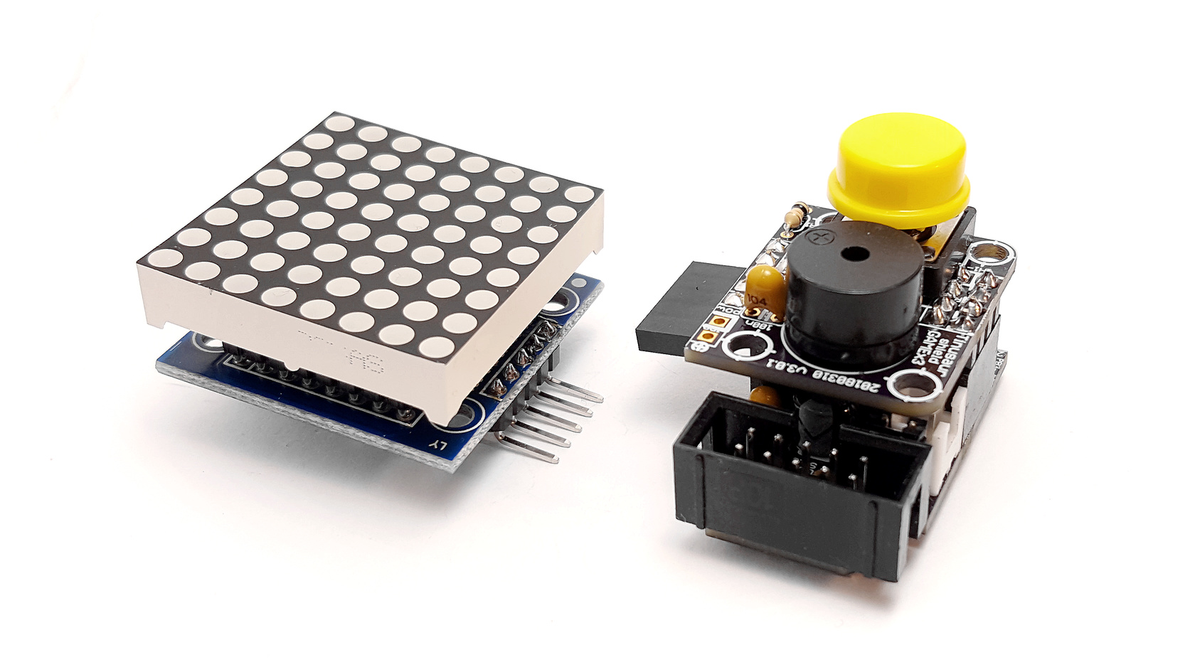
How to connect MAX7219 to an ATtiny85 and work with an 8×8 LED Matrix

What’s our goal?

To connect a MAX7219 based LED Matrix module to an ATtiny85 microcontroller and control the LEDs. Doesn’t sound very complicated, right?

The Titorial

MAX7219tiny MAX7219 ATtiny85

We wrote a short tutorial about how MAX7219 modules work, how to connect them to ATtiny85, and how to write a simple library to work with them

Continue reading the MAX7219 ATtiny85 tutorial here.

Please, leave a comment or suggestion below this blog post.

Updated SSD1306xLED library, fixes, compatibility with SSD1315 and more

SSD1306xLED Testing

Our SSD1306xLED library works well with the SSD1306 displays, it is small as binary code and is very fast.

But, there was a problem …

Several months ago we ordered some displays from the Far East and we expected them to work just fine. Unfortunately, they did not. And the problem was not in our library but with the chips. Instead of SSD1306, it seems they put the not that well known SSD1315 OLED display controller. We found that out by looking closely at the PCB, beneath the LCD glass plate.

ssd1306xled testing
SSD1315 OLED display controller

The testing script was producing the result shown in the picture. Note the bottom lines – they were not redrawn, or not always, at least.

On another display that we’ve got earlier, a few years ago, and that was using the SSD1306 controller the picture was looking good.

SSD1306xLED Testing
SSD1306 OLED display controller

Apparently, the problem was with the display controller. Further experiments proved that.

What made it worse for us was that we’ve discovered that from about a hundred display modules we’ve ordered recently half seemed not compatible with our code. We couldn’t even figure out what exactly was the OLED controller on those modules –
SSD1306 as stated in the description where we bought them, or the SSD1315 looking at the testing scripts results. So, we decided to just fix the problem for both kinds of chips. Easy to say it than to do it.

First attempt

2 months ago. We played with the timing and the speed of the data sent to the modules. Tried a few other things, like reordering the commands sent while drawing. We even moved some of the I2C specific code to a separate library to isolate the potential problems and try to fix the issue. No luck.

Second attempt

2 days ago. We decided to re-do the initialization sequence for the OLED controller. These are the commands that we send to the chip before we start drawing things on the display. We read, again, the Solomon Systech PDF file about the SSD1306 controller – the so-called datasheet. There was a half-baked algorithm of how to initialize the chip. Also, looked at several other libraries to see how they do it. Actually, the “Adafruit_SSD1306.cpp” was a really good example so we used some know-how from it.

Wrote the code. Tested it. And, it worked!

Done!

SSD1306xLED Testing
SSD1306xLED Testing

Some optimizations

There were a couple of TO-DO’s in the source code for the optimization of multiplication by a constant. That could be easily converted to a combination of 1 or more left-bitwise-shift and additions.

void ssd1306tx_char(char ch) {
  uint8_t c = ch - 32; // Convert ASCII code to font data index.
  ssd1306_start_data();
  for (uint8_t i = 0; i < 6; i++) {
    ssd1306_data_byte(pgm_read_byte(&ssd1306tx_font_src[c * 6 + i]));
  }
  ssd1306_stop();
}

We combined the c = ch – 32 and the c * 6 + i and optimized the entire expression.

void ssd1306tx_char(char ch) {
  uint16_t j = (ch << 2) + (ch << 1) - 192;
  ssd1306_start_data();
  for (uint8_t i = 0; i < 6; i++) {
    ssd1306_data_byte(pgm_read_byte(&ssd1306tx_font_src[j + i]));
  }
  ssd1306_stop();
}

That saved us about 30 bytes of binary code and it is probably a bit faster than the multiplication with a subroutine.

We did something similar for the void ssd1306tx_stringxy(const uint8_t *fron_src, uint8_t x, uint8_t y, const char s[]); function but without the left-bitwise-shift as the compiler optimizes the very well the multiplication with numbers that are powers of 2, i.e. 2, 4, 8, etc. In our case – 16. That saved us another 20 bytes of binary code and probably gained some speed.

So, we saved about 50 bytes of machine code and gained some speed. That might not look that much but for a microcontroller with 4096 bytes for code and 1 or 8 MHz CPU that’s about 1.2% less memory usage. And, our library is now a bit faster.

Resources

There are more functions in the SSD1306xLED library such as for printing text and numbers on the screen and drawing images but that will be subject of another article.

The official page of the library (will be):
/software/libraries/ssd1306xled/

Source code is available at:
https://bitbucket.org/tinusaur/ssd1306xled/src

C Library for SSD1306 OLED Display and ATtiny85

C Library for SSD1306 OLED Display and ATtiny85

It isn’t hard to get one of those OLED displays from eBay or another place. They are usually controlled by SSD1306 chip – one of the most popular. Such displays could be used for a number of things – from just learning to control them and showing some text/numbers/graphics, display sensors’ data or even creating a small game.

SSD1306 OLED Display

Back in 2014, we wrote a small library for the ATtiny85 microcontroller to work with such displays and we called it SSD1306xLED after the name of the controlling chip for the display.

Here is a link to check what’s for sale now:
http://www.ebay.com / OLED 128 64

IMPORTANT DISCLAIMERS:

  1. This library works with the display modules that use the I2C protocol. This is important to know since there are other similar displays that use the same SSD1306 controller but communicate over the SPI interface. In that case, our library will not work. We use, in most cases, the modules with 4 pins – GND, Vcc, SCL, SDA.
  2. Although using the I2C interface, our SSD1306xLED library does not implement the I2C protocol but just a subset of it enough to accomplish the task of sending commands and data to the display. This comes with 2 great advantages: (1) it is super fast; (2) is super small – more details about those characteristics will be outlined below.

The library is, of course, open source and all the software is available at https://bitbucket.org/tinusaur/ssd1306xled/

The I2CSW sub-library

This is a small sub-library that implements a subset of the I2C protocols that is necessary to send some commands and data out. I2CSW stands for “I2C Simple Writer” and as its name implies it only writes out.

There are 2 macros to sent the SCL and SDA wires to high and to low, or, or 1 and 0.
I2CSW_HIGH(PORT)
I2CSW_LOW(PORT)

Then, there are 3 low-level functions:
— void i2csw_start(void);
— void i2csw_stop(void);
— void i2csw_byte(uint8_t byte);

The i2csw_start function sets the SCL and SDA pins as output and the “start” condition. In other words, it lets the devices connected to the microcontroller know that we are about to send something out.

The i2csw_stop function sets the “stop” condition. This indicates that we have finished with sending the data. It also set the SDA pin as input so it won’t keep the SDA line at HIGH all the time.

SSD1306 I2C Start and Stop Condition

The i2csw_byte function sends one byte of data out. It is used to send commands and data to the I2C devices – the display in our case.

SSD1306 I2C Acknowledgment Condition

NOTE: The I2CSW library does not handle the acknowledgment condition.

The ssd1306 core functions

There are 4 core functions in the library at the moment:
— void ssd1306_start_command(void);
— void ssd1306_start_data(void);
— void ssd1306_data_byte(uint8_t);
— void ssd1306_stop(void);

The ssd1306_start_command function indicates to the connected I2C devices that we’re about to send commands. This is used to configure the controller o to set some parameters such as the current position on the display.

The ssd1306_start_data function indicates to the connected I2C devices that we’re about to send some data. This is used to send some data to the display controller – like bitmaps or text.

The ssd1306_data_byte function sends 2 bytes of data to the display controller. That is used for both commands and data.

The ssd1306_stop function indicates that we have finished transmitting data.

SSD1306 I2C Write data

The ssd1306 supplementary functions

These are convenience functions:
— void ssd1306_init(void);
— void ssd1306_setpos(uint8_t x, uint8_t y);
— void ssd1306_fill4(uint8_t, uint8_t, uint8_t, uint8_t);

The ssd1306_init function sends a sequence of commands that will initialize the display controller so it will work the way we expect.

The ssd1306_setpos function sets the current position on the display. Sending data after this command will display it at that position.

From the documentation:

Horizontal addressing mode (A[1:0]=00b)

In horizontal addressing mode, after the display RAM is read/written, the column address pointer is increased automatically by 1. If the column address pointer reaches column end address, the column address pointer is reset to column start address and page address pointer is increased by 1. The sequence of movement of the page and column address point for horizontal addressing mode is shown in Figure 10-3. When both column and page address pointers reach the end address, the pointers are reset to column start address and page start address (Dotted line in Figure 10-3.)

Solomon Systech Apr 2008 P 42/59 Rev 1.1 SSD1306
SSD1306 I2C Horizontal addressing mode

The ssd1306_fill4 function fills out the screen with the 4 bytes specified as parameters. The reason for 4 bytes is that it is convenient for filling out with patterns.

There are 3 other functions derived from the ssd1306_fill4 function:
ssd1306_clear() – clears the screen, i.e. fills it out with “0”.
ssd1306_fill(p) – fills the display with the specified byte.
ssd1306_fill2(p1, p2) – fills the display with the 2 specified bytes.

The testing scripts demonstrate the purpose and usage of those functions.

The testing in the “ssd1306xled_test1” folder

Source code at https://bitbucket.org/tinusaur/ssd1306xled/src/default/ssd1306xled_test1/main.c

This testing script demonstrates the use of the functions in the library.

The first section fills out the screen with random values using a Linear congruential generator.

SSD1306 Library SSD1306xLED Testing Script

The second section fills out the screen with a sequential number that creates some patterns on the screen.

SSD1306 Library SSD1306xLED Testing Script

The next section fills out the screen line by line.

SSD1306 Library SSD1306xLED Testing Script

The last section fills out the screen with various patterns.

More functions …

There are more functions in the SSD1306xLED library such as for printing text and numbers on the screen and drawing images but that will be subject of another article.

Please, share your thoughts!

Interfacing a MAX7219 Driven LED Matrix with ATtiny85

LED Matrix 8x8 MAX7219 Assembling

UPDATE 2022: The MAX7219LED8x8 library, now renamed to MAX7219tiny has now a new home at tinusaur.com/libraries/max7219tiny. Check also this MAX7219 & ATtiny85 tutorial to learn how the library works.

The MAX7219 controller manufactured by Maxim Integrated is a compact, serial input/output common-cathode display driver that could interface microcontrollers to 64 individual LEDs, 7-segment numeric LED displays of up to 8 digits, bar-graph displays, etc. Included on-chip are a BCD code-B decoder, multiplex scan circuitry, segment and digit drivers, and an 8×8 static RAM that stores each digit. 

The MAX7219 modules are very convenient to use with microcontrollers such as ATtiny85, or, in our case the Tinusaur Board.

The Hardware

The MAX7219 modules usually look like this:

MAX7219 Module LED Matrix 8x8
MAX7219 Module and LED Matrix 8×8

They have an input bus on one side and output bus on the other. This allows you to daisy chain 2 or more modules, i.e. one after another, to create more complicated setups.

The modules that we are using are capable of connecting in a chain using 5 small jumpers. See the picture below.

MAX7219 Module LED Matrix 8x8
2x MAX7219 Modules Connected

Pinout and Signals

MAX7219 module has 5 pins:

  • VCC – power (+)
  • GND – ground (-)
  • DIN – Data input
  • CS – Chip select
  • CLK – Clock

That means that we need 3 pins on the ATtiny85 microcontroller side to control the module. Those will be:

  • PB0 – connected to the CLK
  • PB1 – connected to the CS
  • PB2 – connected to the DIN

This is sufficient to connect to the MAX7219 module and program it.

The Protocol

Communicating with the MAX7219 is relatively easy – it uses a synchronous protocol which means that for every data bit we send there is a clock cycle that signifies the presence of that data bit.

MAX7219 Timing Diagram

In other words, we send 2 parallel sequences to bits – one for the clock and another for the data. This is what the software does.

The Software

The way this MAX7219 module works is this:

  • We write bytes to its internal register.
  • MAX7219 interprets the data.
  • MAX7219 controls the LEDs in the matrix.

That also means that we don’t have to circle through the array of LEDs all the time in order to light them up – the MAX7219 controller takes care of that. It could also manage the intensity of the LEDs.

So, to use the MAX7219 modules in a convenient way we need a library of functions to serve that purpose.

First, we need some basic functions in order to write to the MAX7219 registers.

  • Writing a byte to the MAX7219.
  • Writing a word (2 bytes) to the MAX7219.

The function that writes one byte to the controller looks like this:

void max7219_byte(uint8_t data) {
    for(uint8_t i = 8; i >= 1; i--) {
        PORTB &= ~(1 << MAX7219_CLK);   // Set CLK to LOW
        if (data & 0x80)                // Mask the MSB of the data
            PORTB |= (1 << MAX7219_DIN);    // Set DIN to HIGH
        else
            PORTB &= ~(1 << MAX7219_DIN);   // Set DIN to LOW
        PORTB |= (1 << MAX7219_CLK);        // Set CLK to HIGH
        data <<= 1;                     // Shift to the left
    }
}

Now that we can send bytes to the MAX7219 we can start sending commands. This is done by sending 2 byes – 1st for the address of the internal register and the 2nd for the data we’d like to send.

There is more than a dozen of register in the MAX7219 controller.

MAX7219 Registers and Commands

Sending a command, or a word, is basically sending 2 consecutive bytes. The function implementing that is very simple.

void max7219_word(uint8_t address, uint8_t data) {
    PORTB &= ~(1 << MAX7219_CS);    // Set CS to LOW
    max7219_byte(address);          // Sending the address
    max7219_byte(data);             // Sending the data
    PORTB |= (1 << MAX7219_CS);     // Set CS to HIGH
    PORTB &= ~(1 << MAX7219_CLK);   // Set CLK to LOW
}

It is important to note here the line where we bring the CS signal back to HIGH – this marks the end of the sequence – in this case, the end of the command. A similar technique is used when controlling more than one matrix connected in a chain.

Next step, before we start turning on and off the LEDs, is to initialize the MAX7219 controller. This is done by writing certain values to certain registers. For convenience, while coding it we could put the initialization sequence in an array.

uint8_t initseq[] = {
    0x09, 0x00, // Decode-Mode Register, 00 = No decode
    0x0a, 0x01, // Intensity Register, 0x00 .. 0x0f
    0x0b, 0x07, // Scan-Limit Register, 0x07 to show all lines
    0x0c, 0x01, // Shutdown Register, 0x01 = Normal Operation
    0x0f, 0x00, // Display-Test Register, 0x00 = Normal Operation
};

We just need to send the 5 commands above in a sequence as address/data pairs.

Next step – lighting up a row of LEDs.

This is very simple – we just write one command where 1st byte is the address (from 1 to 8) and the 2nd byte is the 8 bits representing the 8 LEDs in the row.

void max7219_row(uint8_t address, uint8_t data) {
    if (address >= 1 && address <= 8) max7219_word(address, data);
}

It is important to note that this will work for 1 matrix only. If we connect more matrices in a chain they will all show the same data. The reason for this is that after sending the command we bring the CS signal back to HIGH which causes all the MAX7219 controllers in the chain to latch and show whatever the last command was.

Testing

This is a simple testing program that lights up a LED on the first row (r=1) on the right-most position, then moves that on the left until it reaches the left-most position, then does the same on one row up (r=2) )until it reaches the top (r=8).

max7219_init();
for (;;) {
    for (uint8_t r = 1; r <= 8; r++) {
        uint8_t d = 1;
        for (uint8_t i = 9; i > 0; i--) {
            max7219_row(r, d);
            d = d << 1;
            _delay_ms(50);
        }
    }
}
MAX7219 Testing MAX7219LED8x8 Library
MAX7219 Testing

This testing code doesn’t do much but it demonstrates how to communicate with the MAX7219 controller.

The MAX7219LED8x8 Library

All of the functions mentioned above are part of the MAX7219LED8x8 library. Its source code is available at https://bitbucket.org/tinusaur/max7219led8x8.

The Tinusaur Shield GAMEx3

If you already have a Tinusaur Board we have the Shield GAMEx3 for it to connect a MAX7219 module easier to your ATtiny85 microcontroller.

Shield GAMEx3
Shield GAMEx3

The Gametinu Project

The Gametinu is a small game platform that you could build yourself using the Shield GAMEx3 and a few more parts and tools.

Gametinu
Gametinu

References

MAX7219 specification and datasheet:


This article is a rewritten version of another article from 2014:
MAX7219 driver for LED Matrix 8×8.


Launching Crowdfunding Campaign in January

Tinusaur OLED SSD1306xLED Crowdfunding Campaign

It looks like that our most popular software library is the SSD1306xLED. This is a library for working with OLED displays based on the SSD1306 controller. So, we decided to create a Tinusaur shield to carry an OLED display and we’re thinking about putting it up for crowdfunding this January.

What could you do it a Tinusaur Board and an OLED display?

There is an internal temperature sensor built into the ATtiny85 microcontroller and you don’t need any external components to use it. You can read its value and show it on the display.

Tinusaur OLED SSD1306xLED
Tinusaur OLED SSD1306xLED measuring temperature and voltage

We’ve figured a way to measure the battery level (or the power supply voltage) connected to the ATtiny85 microcontroller by using the PB5 (that is the RESET pin, yes) and one additional resistor. It is not very precise but could give you an indication, at least.

DHT11 module
DHT11 Module

You could also connect one of those popular DHT11 sensor modules, measure temperature and humidity and show it on the screen.

BM180 module
BM180 Module

You could also connect the Bosch BMP180 sensor module and measure barometric pressure and temperature, and show it on the screen. That will also allow you to calculate the altitude – pretty neat, isn’t it?

The official announcement with information about the start date, goals and other details is coming up in early January.

BLOCKTINU – The Development Environment for the Tinusaur – ATtiny85 Microcontroller Board

BLOCKTINU - The Development Environment for the Tinusaur

The Blocktinu is the development environment for your Tinusaur microcontroller boards where you could use blocks to produce real C programming language source code.

As you move your blocks (on the left) to implement your algorithms, the source code (on the right) will be automatically updated. Pretty neat, huh?

Now you can start learning the C programming language by playing with the blocks and looking at the changes in the source code that has been generated.

Once your program is ready it will be compiled in the cloud so no installation of any SDK will be necessary. The resulting binary code for the ATtiny85 microcontroller will be returned back to you.

The Blocktinu is part of the Tinusaur project.

The Blocktinu and the Tinusaur are open source projects. Both the software and the hardware!

The Blocktinu is almost ready for public use.

The Blocktinu is part of the Tinusaur crowdfunding campaign that we have launched on January 22nd, 2018.

Support our crowdfunding campaign. Get yourself a Tinusaur microcontroller board. You will receive early access to the Blocktinu development environment.

ANNOUNCEMENT: The Tinusaur Crowdfunding Campaign on January 22nd 2018

Tinusaur Crowdfunding Campaign on January 22nd 2018

Campaign link: http://igg.me/at/tinusaur
Project link: /

  1. A small robot car that you could build yourself and program it to follow a black line on the floor.
  2. A small game platform, that you could build and program yourself.

Those are the Tinusaur project goodies. They can help you learn, teach and make things with microcontrollers, and have fun at the same time. This is what the Tinusaur project is about.

Next Monday, on January 22nd we are launching a crowdfunding campaign to make more of those fun projects.

Join us at http://igg.me/at/tinusaur and subscribe for updates about the launch.


GAMETINU – Small Game Platform, Powered by the Tinusaur – ATtiny85 Microcontroller Board

GAMETINU - Small Game Platform, Powered by the Tinusaur - ATtiny85 Microcontroller Board

The Gametinu is a small game platform that you could build yourself. But don’t worry, it isn’t that complicated. This circuit is very simple, and there are very few things that could go wrong. The “brain” of the Gametinu is the Tinusaur board, powered by the popular Atmel ATtiny85 microcontroller.

Once your Gametinu is ready you can start programming it.

On the frame, you have a small 64 LED display. Beneath the display, you have a button and a buzzer.

You can program the Gametinu to run one of those no-player games such as the “Conway’s Game of Life“. You could also program it to run simple one-button games such as the Stacker Game.

The Gametinu is part of the Tinusaur project. It is important to mention that the Tinusaur and the Gametinu are open source projects? Both the software and the hardware! You can buy all parts, fabricate the PCBs, and assemble them yourself.

The Gametinu is almost ready for production. It is now part of the crowdfunding campaign that we are launching on January 22nd, 2018.

Sounds interesting?

Subscribe to get updates about the launch. Link to the campaign: http://igg.me/at/tinusaur

More information about the Gametinu will be posted on its page.


CARTINU – Small Robot Car, Powered by the Tinusaur – ATtiny85 Board

CARTINU - Small Robot Car, Powered by the Tinusaur - ATtiny85 Board

The Cartinu is a small robot car that you could build yourself. But don’t worry! It isn’t that complicated – this circuit, is so simple, that there are very few things that could go wrong. The “brain” of the Cartinu is the Tinusaur board that is powered by the popular Atmel ATtiny85 microcontroller.

Once your Cartinu is ready you could start programming it.

On the chassis, you have 2 powerful planetary gear motors. You also have 2 infrared proximity sensors on the bottom of the chassis. That allows you to program the Cartinu to follow a black line on the floor.

The Cartinu is part of the Tinusaur project. It is important to mention that the Tinusaur and the Cartinu are an open source project? Both the software and the hardware! You can buy all parts, fabricate the PCBs, and assemble them yourself.

The Cartinu is almost ready for production and is part of the crowdfunding campaign that we are launching on January 22nd 2018.

Sounds interesting?

Subscribe to get updates about the launch.


More information about the Cartinu will be posted on its page.