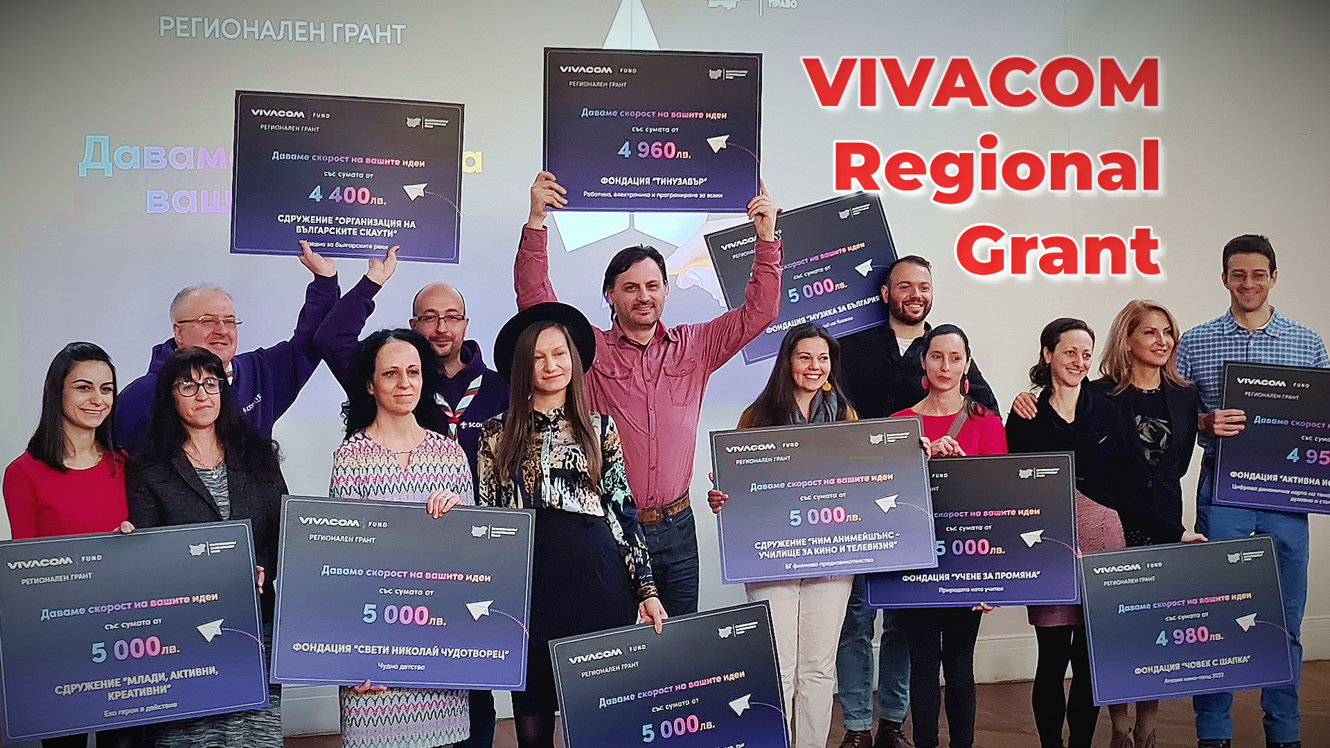
Tinusaur Foundation won funding for robotics workshops in 8 small towns in Veliko Tarnovo Municipality

VIVACOM Regional Grant

In the coming months of 2022, we will introduce children from Veliko Tarnovo to educational technologies and methodologies of the future

Our foundation’s project “Robotics, Electronics and Programming for Everyone” won BGN 4960.00 under the program “VIVACOM Regional Grant“. We will use it to purchase materials and organize robotics workshops for beginners in schools in the villages of Ledenik, Tserova Koria, Vodoley, Balvan, the town of Debelets, and Kilifarevo.

Tinusaur foundation - VIVACOM Regional Grant

The funds will be used to purchase six laptops, tools, equipment, and supplies. Those wishing to participate in the activities will assemble a Tinusaur Kids.Micro electronic board with a soldering iron. This board is a miniature computer with which we will learn to program. At the end of the workshop, we will create an interesting project that may even be useful in our daily lives.

Participants get to keep everything they’ve made during the workshop. Later they can use it in school projects or competitions. Students will have the opportunity to continue their studies with the help of the free online materials that we have prepared.

The project is expected to start in early June for the International  Children’s Day – June 1. It will be implemented in stages in the individual schools to cover a total of 60 students. For us, these are 60 families who (in most cases) will touch technology and modern education for the first time. We will give them confidence that the place where they live can provide them with opportunities no worse than those in the big city.

Opportunity for teachers

We will invite teachers from each school during the workshops, who will also learn about the benefits of using modern teaching aids. We will offer a scholarship from our foundation for those of them who show the most significant interest and motivation. They will participate in a training organized by us in collaboration with our partners. It will allow them to continue the workshops in the future or implement the activities in regular classes.

We are sure that such an event will be a unique experience for all participants – students, teachers, and parents, and will inspire them to continue to develop in this direction. We want to continue this initiative in the future in other schools in the region of Veliko Tarnovo.

The project “Robotics, Electronics and Programming for Everyone” is implemented under the “VIVACOM Regional Grant” program.

Launched crowdfunding campaign for the Tinusaur OLED Display Kit

Tinusaur OLED Display Кit

We have just launched our crowdfunding campaign at Crowd Supply for the Tinusaur OLED Display Kit – a bundle of boards and modules that allows you to connect an ATtiny85 microcontroller to an SSD1306 OLED display. This is a kit so you have to assemble the boards yourself by soldering the parts to the PCB thus start learning about electronics and physics. It might sound complicated at first but these Tinusaur boards are very easy to assemble using the guides and tutorials that we provide. Once all the boards are assembled you could connect a DHT11 sensor module, measure temperature and humidity and show the results on the screen.

Tinusaur OLED Display Кit

With the Tinusaur OLED Display Kit, you get everything you need to start: the Tinusaur main board with the ATtiny85 microcontroller, the LED shield for test and learning, the OLED display shield, the SSD1306 OLED display, the DHT11 sensor module, a LiPo battery kit, and, a USBasp programmer.

The Tinusaur is an Open Source project – both the software and the hardware. Our own library for with the display, called SSD1306xLED, is considered one of the fastest for that display and microcontroller.

Check out the campaign page for details!

Interfacing a MAX7219 Driven LED Matrix with ATtiny85

LED Matrix 8x8 MAX7219 Assembling

UPDATE 2022: The MAX7219LED8x8 library, now renamed to MAX7219tiny has now a new home at tinusaur.com/libraries/max7219tiny. Check also this MAX7219 & ATtiny85 tutorial to learn how the library works.

The MAX7219 controller manufactured by Maxim Integrated is a compact, serial input/output common-cathode display driver that could interface microcontrollers to 64 individual LEDs, 7-segment numeric LED displays of up to 8 digits, bar-graph displays, etc. Included on-chip are a BCD code-B decoder, multiplex scan circuitry, segment and digit drivers, and an 8×8 static RAM that stores each digit. 

The MAX7219 modules are very convenient to use with microcontrollers such as ATtiny85, or, in our case the Tinusaur Board.

The Hardware

The MAX7219 modules usually look like this:

MAX7219 Module LED Matrix 8x8
MAX7219 Module and LED Matrix 8×8

They have an input bus on one side and output bus on the other. This allows you to daisy chain 2 or more modules, i.e. one after another, to create more complicated setups.

The modules that we are using are capable of connecting in a chain using 5 small jumpers. See the picture below.

MAX7219 Module LED Matrix 8x8
2x MAX7219 Modules Connected

Pinout and Signals

MAX7219 module has 5 pins:

  • VCC – power (+)
  • GND – ground (-)
  • DIN – Data input
  • CS – Chip select
  • CLK – Clock

That means that we need 3 pins on the ATtiny85 microcontroller side to control the module. Those will be:

  • PB0 – connected to the CLK
  • PB1 – connected to the CS
  • PB2 – connected to the DIN

This is sufficient to connect to the MAX7219 module and program it.

The Protocol

Communicating with the MAX7219 is relatively easy – it uses a synchronous protocol which means that for every data bit we send there is a clock cycle that signifies the presence of that data bit.

MAX7219 Timing Diagram

In other words, we send 2 parallel sequences to bits – one for the clock and another for the data. This is what the software does.

The Software

The way this MAX7219 module works is this:

  • We write bytes to its internal register.
  • MAX7219 interprets the data.
  • MAX7219 controls the LEDs in the matrix.

That also means that we don’t have to circle through the array of LEDs all the time in order to light them up – the MAX7219 controller takes care of that. It could also manage the intensity of the LEDs.

So, to use the MAX7219 modules in a convenient way we need a library of functions to serve that purpose.

First, we need some basic functions in order to write to the MAX7219 registers.

  • Writing a byte to the MAX7219.
  • Writing a word (2 bytes) to the MAX7219.

The function that writes one byte to the controller looks like this:

void max7219_byte(uint8_t data) {
    for(uint8_t i = 8; i >= 1; i--) {
        PORTB &= ~(1 << MAX7219_CLK);   // Set CLK to LOW
        if (data & 0x80)                // Mask the MSB of the data
            PORTB |= (1 << MAX7219_DIN);    // Set DIN to HIGH
        else
            PORTB &= ~(1 << MAX7219_DIN);   // Set DIN to LOW
        PORTB |= (1 << MAX7219_CLK);        // Set CLK to HIGH
        data <<= 1;                     // Shift to the left
    }
}

Now that we can send bytes to the MAX7219 we can start sending commands. This is done by sending 2 byes – 1st for the address of the internal register and the 2nd for the data we’d like to send.

There is more than a dozen of register in the MAX7219 controller.

MAX7219 Registers and Commands

Sending a command, or a word, is basically sending 2 consecutive bytes. The function implementing that is very simple.

void max7219_word(uint8_t address, uint8_t data) {
    PORTB &= ~(1 << MAX7219_CS);    // Set CS to LOW
    max7219_byte(address);          // Sending the address
    max7219_byte(data);             // Sending the data
    PORTB |= (1 << MAX7219_CS);     // Set CS to HIGH
    PORTB &= ~(1 << MAX7219_CLK);   // Set CLK to LOW
}

It is important to note here the line where we bring the CS signal back to HIGH – this marks the end of the sequence – in this case, the end of the command. A similar technique is used when controlling more than one matrix connected in a chain.

Next step, before we start turning on and off the LEDs, is to initialize the MAX7219 controller. This is done by writing certain values to certain registers. For convenience, while coding it we could put the initialization sequence in an array.

uint8_t initseq[] = {
    0x09, 0x00, // Decode-Mode Register, 00 = No decode
    0x0a, 0x01, // Intensity Register, 0x00 .. 0x0f
    0x0b, 0x07, // Scan-Limit Register, 0x07 to show all lines
    0x0c, 0x01, // Shutdown Register, 0x01 = Normal Operation
    0x0f, 0x00, // Display-Test Register, 0x00 = Normal Operation
};

We just need to send the 5 commands above in a sequence as address/data pairs.

Next step – lighting up a row of LEDs.

This is very simple – we just write one command where 1st byte is the address (from 1 to 8) and the 2nd byte is the 8 bits representing the 8 LEDs in the row.

void max7219_row(uint8_t address, uint8_t data) {
    if (address >= 1 && address <= 8) max7219_word(address, data);
}

It is important to note that this will work for 1 matrix only. If we connect more matrices in a chain they will all show the same data. The reason for this is that after sending the command we bring the CS signal back to HIGH which causes all the MAX7219 controllers in the chain to latch and show whatever the last command was.

Testing

This is a simple testing program that lights up a LED on the first row (r=1) on the right-most position, then moves that on the left until it reaches the left-most position, then does the same on one row up (r=2) )until it reaches the top (r=8).

max7219_init();
for (;;) {
    for (uint8_t r = 1; r <= 8; r++) {
        uint8_t d = 1;
        for (uint8_t i = 9; i > 0; i--) {
            max7219_row(r, d);
            d = d << 1;
            _delay_ms(50);
        }
    }
}
MAX7219 Testing MAX7219LED8x8 Library
MAX7219 Testing

This testing code doesn’t do much but it demonstrates how to communicate with the MAX7219 controller.

The MAX7219LED8x8 Library

All of the functions mentioned above are part of the MAX7219LED8x8 library. Its source code is available at https://bitbucket.org/tinusaur/max7219led8x8.

The Tinusaur Shield GAMEx3

If you already have a Tinusaur Board we have the Shield GAMEx3 for it to connect a MAX7219 module easier to your ATtiny85 microcontroller.

Shield GAMEx3
Shield GAMEx3

The Gametinu Project

The Gametinu is a small game platform that you could build yourself using the Shield GAMEx3 and a few more parts and tools.

Gametinu
Gametinu

References

MAX7219 specification and datasheet:


This article is a rewritten version of another article from 2014:
MAX7219 driver for LED Matrix 8×8.


Launching Crowdfunding Campaign in January

Tinusaur OLED SSD1306xLED Crowdfunding Campaign

It looks like that our most popular software library is the SSD1306xLED. This is a library for working with OLED displays based on the SSD1306 controller. So, we decided to create a Tinusaur shield to carry an OLED display and we’re thinking about putting it up for crowdfunding this January.

What could you do it a Tinusaur Board and an OLED display?

There is an internal temperature sensor built into the ATtiny85 microcontroller and you don’t need any external components to use it. You can read its value and show it on the display.

Tinusaur OLED SSD1306xLED
Tinusaur OLED SSD1306xLED measuring temperature and voltage

We’ve figured a way to measure the battery level (or the power supply voltage) connected to the ATtiny85 microcontroller by using the PB5 (that is the RESET pin, yes) and one additional resistor. It is not very precise but could give you an indication, at least.

DHT11 module
DHT11 Module

You could also connect one of those popular DHT11 sensor modules, measure temperature and humidity and show it on the screen.

BM180 module
BM180 Module

You could also connect the Bosch BMP180 sensor module and measure barometric pressure and temperature, and show it on the screen. That will also allow you to calculate the altitude – pretty neat, isn’t it?

The official announcement with information about the start date, goals and other details is coming up in early January.

We have just made Blocktinu Windows app better

Here are the changes:

  • Fixed bug that caused an error message when there is a  space in the name of the HEX file or in the path to your user folder.

Now, the juicy part …

Blocktinu Windows Desktop Application

This is the first version of the Blocktinu Windows Desktop Application.

  • How, as part of the app, there are 2 pre-compiled programs that you could conveniently use to test your newly assembled board.
    1. Just an empty app that will allow you to see if the binary code goes from the your computer (if drivers have been installed correctly) through the USBasp ISP programmer and, into the microcontroller. That could also be used to check if the board has been assembled correctly.
    2. The other one is a simple app that will make any LED connected (through a resistor, of course) to any of the 5 available I/O pins – PB0, PB1, PB2, PB3, PB4 – blink. That could be used to test if the boards and the shields have been assembled correctly.

Using these 2 pre-compiled programs does not require anything that just pressing the “Upload” buttons on the screen – no writing code, no compiling, building or downloading.

The latest version is available for download at: https://bitbucket.org/tinusaur/blocktinu-tools-win/downloads/blocktinu-tools-1.1.1-install.zip

More and up to date information is also available at blocktinu.com.

Please, let us know what do you think.

We have just passed the 10% mark!

We have just passed the 10% mark!

Dear friends,

Thanks a lot for your contribution to the campaign and for the support of our project. We have just passed the 10% mark! As usual, our campaign goes slow but steady.

Please, if you can, spread the word about our project, share it with people that might be interested.

All the best,
Neven Boyanov
The TINUSAUR Team.

https://igg.me/at/tinusaur


ANNOUNCEMENT: The Tinusaur Crowdfunding Campaign on January 22nd 2018

Tinusaur Crowdfunding Campaign on January 22nd 2018

Campaign link: http://igg.me/at/tinusaur
Project link: /

  1. A small robot car that you could build yourself and program it to follow a black line on the floor.
  2. A small game platform, that you could build and program yourself.

Those are the Tinusaur project goodies. They can help you learn, teach and make things with microcontrollers, and have fun at the same time. This is what the Tinusaur project is about.

Next Monday, on January 22nd we are launching a crowdfunding campaign to make more of those fun projects.

Join us at http://igg.me/at/tinusaur and subscribe for updates about the launch.