GAMETINU – Small Game Platform, Powered by the Tinusaur – ATtiny85 Microcontroller Board

GAMETINU - Small Game Platform, Powered by the Tinusaur - ATtiny85 Microcontroller Board

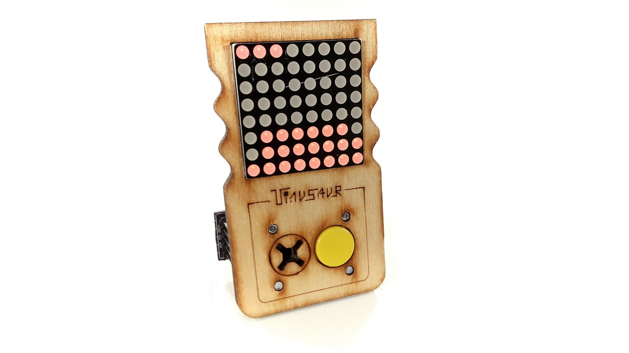
The Gametinu is a small game platform that you could build yourself. But don’t worry, it isn’t that complicated. This circuit is very simple, and there are very few things that could go wrong. The “brain” of the Gametinu is the Tinusaur board, powered by the popular Atmel ATtiny85 microcontroller.

Once your Gametinu is ready you can start programming it.

On the frame, you have a small 64 LED display. Beneath the display, you have a button and a buzzer.

You can program the Gametinu to run one of those no-player games such as the “Conway’s Game of Life“. You could also program it to run simple one-button games such as the Stacker Game.

The Gametinu is part of the Tinusaur project. It is important to mention that the Tinusaur and the Gametinu are open source projects? Both the software and the hardware! You can buy all parts, fabricate the PCBs, and assemble them yourself.

The Gametinu is almost ready for production. It is now part of the crowdfunding campaign that we are launching on January 22nd, 2018.

Sounds interesting?

Subscribe to get updates about the launch. Link to the campaign: http://igg.me/at/tinusaur

More information about the Gametinu will be posted on its page.


CARTINU – Small Robot Car, Powered by the Tinusaur – ATtiny85 Board

CARTINU - Small Robot Car, Powered by the Tinusaur - ATtiny85 Board

The Cartinu is a small robot car that you could build yourself. But don’t worry! It isn’t that complicated – this circuit, is so simple, that there are very few things that could go wrong. The “brain” of the Cartinu is the Tinusaur board that is powered by the popular Atmel ATtiny85 microcontroller.

Once your Cartinu is ready you could start programming it.

On the chassis, you have 2 powerful planetary gear motors. You also have 2 infrared proximity sensors on the bottom of the chassis. That allows you to program the Cartinu to follow a black line on the floor.

The Cartinu is part of the Tinusaur project. It is important to mention that the Tinusaur and the Cartinu are an open source project? Both the software and the hardware! You can buy all parts, fabricate the PCBs, and assemble them yourself.

The Cartinu is almost ready for production and is part of the crowdfunding campaign that we are launching on January 22nd 2018.

Sounds interesting?

Subscribe to get updates about the launch.


More information about the Cartinu will be posted on its page.


Introducing the BLOCKTINU – programming with blocks for the Tinusaur and ATtiny85

Blocktinu for Tinusaur

Dragging and dropping blocks on a web page that generates real C code which gets compiled on the cloud and then uploaded locally to your microcontroller.

Does that sound interesting to you?

Well, we’ve done it. Kind of. We called it Blocktinu.

A couple of weeks ago me (Neven Boyanov) and my friend Geroge (Georgi Marinov) participated in the #BG10xEU hackathon in Sofia and the idea that we developed and presented was just that. Within the given 24 hrs we managed to develop the initial version of most of the modules, including a browser extension for Google Chrome for handling the communication between the cloud and the local machine. At the moment the only missing part is the piece that invokes the avrdude from within the browser extension.

IMPORTANT: Please note that this is just the beginning and there is still work to be done.

We will have the source code (free and open) at this location: https://bitbucket.org/tinusaur/blocktinu.

UPDATE (2021): Bitbucket no longer hosts our projects. 🙁
Our source code is available at
— https://gitlab.com/tinusaur
— https://github.com/tinusaur (mirror)

The project will be located here: /projects/blocktinu/.

The Blocktinu is using the Blockly library for handling the block in a browser.

Below is a high-level architecture diagram.

Blocktinu for Tinusaur Architectural Diagram

PS: We did not get any prizes, the judges did not find the idea interesting enough. 🙁

UPDATED: DS1307 Library

The functions were moved to separate files in the DS1307tiny library.

The sample code in the ds1307tiny_test1 module looks cleaner now. The output should be something like this …

DS1307 Serial Real-Time Clock USITWIX ATtiny85

Note that one of the challenges working with a real-time clock the the DS1307 is to set it up with the correct time at the beginning.

  • One way is to do that programmatically – write a program for the microcontroller that will set the clock to specific date & time and run that program right at the specified in the code date & time.
  • Another way of doing taht is to use some sort of USB-to-I2C module and set the date & time from the computer. Such modules exist but they are kind of expensive for the simeple thing they do.
    Ref: http://www.ebay.com/sch/i.html?LH_BIN=1&_nkw=USB+to+I2C&_sop=15

References

Source code available at: https://bitbucket.org/tinusaur/ds1307tiny

More information about the library will be available at its own page: DS1307tiny


Working with DS1307 Real-time Clock and ATtiny85 using USITWIX Library

DS1307 Serial Real-Time Clock USITWIX Tinusaur.

Working with the DS1307 Serial Real-Time Clock using the USITWIX library for I2C / TWI on Atmel ATtiny85 / Tinusaur.

Let’s see how can we work with the DS1307 serial real-time clock using the USITWIX library for I2C / TWI on Atmel ATtiny85 / Tinusaur.

Bellow is the testing setup.

NOTE: We need the USB-to-Serial just for debugging – it isn’t essential part of the setup.

DS1307 Serial Real-Time Clock USITWIX Tinusaur.

There is no library yet to do that but with in the testing code there are few functions that could do the job.

Here is brief a description of the functions:

  • uint8_t ds1307_read_reg8(uint8_t reg_addr) – reads one byte of data from the specified register.
  • uint8_t ds1307_write_reg8(uint8_t reg_addr, uint8_t reg_data) – write one byte of data to the specified register.
  • uint8_t ds1307_init(void) – initializes the circuit by writing specific data into the registers.
  • uint8_t ds1307_setdatetime(uint16_t year, uint8_t month, uint8_t date, uint8_t weekday, uint8_t hour, uint8_t min, uint8_t sec) – sets date and time.
  • uint8_t ds1307_adjust(void) – this is helper function – it sets the date & time to a specific value – let’s not forget that a brand new circuit does not have correct date and time set.

DS1307 Serial Real-Time Clock ModuleThere are 2 additional functions that are used to convert data byte to and from BCD format.

  • static uint8_t bcd2bin (uint8_t val)
  • static uint8_t bin2bcd (uint8_t val)

This is direct link to the source code of the testing program:
https://bitbucket.org/tinusaur/ds1307tiny/src/default/ds1307tiny_test1/main.c

Source code available at: https://bitbucket.org/tinusaur/ds1307tiny

More information about the library will be available at its own page: DS1307tiny

Working with BMP180 Pressure Sensor and ATtiny85 using USITWIX Library

USITWIX – Using USI as TWI / I2C

In our previous post “USITWIX – Using UART as TWI / I2C” we looked at the USITWIX library that implements TWI / I2C communication between а  ATtiny85 micro-controller and peripherals. Let’s see now how we can use that library to work with the BOSCH BMP180 atmospheric pressure sensor and a ATtiny85/Tinusaur boards.

The BMP180tiny Library

So, we wrote a simple library (called it BMP180tiny) that uses USITWIX to read and write from/to BMP180 registers, retrieve the measurements, do some additional calculations and produce result suitable for use in an application.

Setup

Here’s the setup:

BMP180 with Tinusaur ATtiny85 USITWIX

NOTE: We need the USB-to-Serial just for debugging – it isn’t essential part of the setup.

Here is a short fragment of initialization code

uint8_t bmp180_result;
if ((bmp180_result = bmp180_init()) != BMP180_RESULT_SUCCESS)
{
return -1;
}

And here is now to use the functions …

// Read raw temperature
uint16_t temp_rawdata = bmp180_read_temp_raw();

uint16_t temp_10x = bmp180_read_temp10x();
// temp_10x holds the result dC, i.e. 123 means 12.3 Celsius

// Read raw pressure
int32_t pres_rawdata = bmp180_read_pres_raw();

// Read pressure
int32_t pres = bmp180_read_pres();
int16_t pres_hpa = pres / 100;
// pres_hpa holds the result in hPa (hectopascals)

// Read altitude
int32_t alt_x = bmp180_read_alt_x();
int16_t alt_dm = alt_x / 100;
// alt_dm holds the result in dm (decimeters)

The debugging output would look something like this …

t:raw=28622; t(dC)=253; p:raw/hi=5; p:raw/lo=4940; p(Pa)/hi=1; p(Pa)/lo=33948; p(hPa)=994; a/lo=24222; a(dm)=1552;
t:raw=28624; t(dC)=253; p:raw/hi=5; p:raw/lo=4964; p(Pa)/hi=1; p(Pa)/lo=33933; p(hPa)=994; a/lo=24307; a(dm)=1553;
t:raw=28623; t(dC)=253; p:raw/hi=5; p:raw/lo=4951; p(Pa)/hi=1; p(Pa)/lo=33939; p(hPa)=994; a/lo=22619; a(dm)=1536;
t:raw=28624; t(dC)=253; p:raw/hi=5; p:raw/lo=4942; p(Pa)/hi=1; p(Pa)/lo=33940; p(hPa)=994; a/lo=24560; a(dm)=1556;

NOTE: This is generated using OWOWOD library and hardware (not required by the library itself to work)

References

The source code is available at https://bitbucket.org/tinusaur/bmp180tiny.
— The library is in the “bmp180tiny” folder.
— A sample code could found in the “bmp180tiny_test1” folder.

The page about BMP180tiny and articles about BMP180tiny.

The page about USITWIX and articles about USITWIX.

New Library: USITWIX – Using USI as TWI / I2C

Attiny85 Tinusaur USI TWI I2C BMP180 Variometer

As we know, there’s no I²C on ATtiny85, not even the TWI (Two Wire Interface, which is basically I2C with a different name) that some other Atmel chips have, so I had to write my own that takes advantage on the built-in USI unit. This library is called USITWIX and will be presented in this blog post.

Of course, I used other people’s work write mine and they’re references in the source code.

The primary source is the Atmel application note AVR312: Using the USI module as a I2C slave that explains how to use the  built-in USI unit as I2C slave.

The source code is already available at https://bitbucket.org/tinusaur/usitwix.

Some important code fragments

Although the TWI and I2C is a synchronous communication protocol it still requires precise timing.

In the code there are few places where some fixed time intervals are specified and this is in the usitwim.h file:

#define T2_TWI 5 // >4,7us
#define T4_TWI 4 // >4,0us

These may need to be adjusted if the CPU runs at a frequency different than default 1 MHz.

Using the USITWIX library

Paragliding

The BMP180TINY is another library for working with the BOSCH BMP180 atmospheric pressure sensor.The source code is available at https://bitbucket.org/tinusaur/bmp180tiny along with some samples.

There is also a Variometer project that uses those libraries to produce audible measurements of the changes in the altitude by measuring the atmospheric pressure and taking into account the temperature. Such tools, or instruments, are often used by paragliders.

Video here:
https://www.youtube.com/watch?v=6JTnYuJGo4w

References

Here are some references to sources that I used while working on this project.

AVR312: Using the USI module as a I2C slave
http://www.atmel.com/Images/doc2560.pdf
C-code driver for TWI slave, with transmit and receive buffers; Compatible with I2C protocol; Interrupt driven, detection and transmission/reception; Wake up from all sleep mode, including Power Down.

TINY USI Interface in I2C mode and the AVR312 Appnote
http://www.aca-vogel.de/TINYUSII2C_AVR312/APN_TINYUSI_I2C.html
What’s wrong with the AVR Appnote?

ATTiny USI I2C Introduction – A powerful, fast, and convenient communication interface for your ATTiny projects!
http://www.instructables.com/id/ATTiny-USI-I2C-The-detailed-in-depth-and-infor/
I2C, it’s a standard that’s been around for around 20 years and has found uses in nearly every corner of the electronics universe. It’s an incredibly useful technology for us microcontroller hobbyists but can seem daunting for new users. This tutorial will solve that problem, first by reviewing what I2C is and how it works, then by going in-depth on how to implement I2C in Atmel’s ATTiny USI (Universal Serial Interface) hardware.

I2C Bus for ATtiny and ATmega
http://www.instructables.com/id/I2C_Bus_for_ATtiny_and_ATmega/
This two wire interface is formally known as the Inter-Integrated Circuit bus, or just the I2C bus and was invented by NXP when it was still Philips Semiconductors. If you’re reading this Instructable then you’ve probably heard of the I2C bus and may even have used it on a PIC or other microcontroller. While conceptually very simple, and supported by hardware resources on the AVRs, software drivers are still necessary to use the I2C bus. Atmel provides Application Notes (see the Resources later in this Instructable), but these are incomplete and don’t show any examples beyond communicating with another AVR device.

The OWOWOD Library

OWOWOD is One Wire / One Way Output for Debugging library. It allows you to output text from the Tinusaur (ATtiny85 microcontroller or other similar), though USB-to-Serial or TTL converter (based on PL2303, CH340G or similar) and to the computer screen using COM port monitoring tool.

Why one would need something like that?

It would’ve been nice if it was possible to write something li this …

debugging_print("working, x=%i", x);

… and see the output on a computer. Great for debugging and other things.

Unfortunately ,there is no easy way of doing that – in fact not possible with the standard tools used to work with the ATtiny85. The problem is this: (1) those micro-controllers have too few I/O ports; and (2) most of the programmers (ex.: USBasp) do not offer that kind of communication between the micro-controller and the computer, i.e. there is no 2-way communication.

USB to Serial TTL

There are some solution and the OWOWOD library is just one of them. It uses an additional hardware component – USB-to-Serial converter also known as USB TTL Converter. They are very inexpensive, easy to find and work with.

The OWOWOD Library could do that.

Tinusaur connected to USB-to-Serial PL2303 using OWOWOD

For this to work we need …

  • Micro-controller
  • USB-to-Serial converter
  • Computer

The Library works like this …

  • When you use a library function like owowod_print_char(‘U’) it will start sending sending the bits of the ‘U’ byte (hex: 0x55, bin: 01010101) in series, i.e. one bit after another, through one of the microcontroller pins – for instance PB3.
  • At the other end of the wire there is USB-to-Serial converter that will take the individual 01010101 bits and re-compose them back into one byte as 0x55.
  • Then the USB-to-Serial converter will send that ‘U’ byte (0x55) to the computer USB port.
  • The computer sees the USB-to-Serial as a Serial COM Port port, so it reads that ‘U’ byte.
  • Using another program on the computer we get that ‘U’ byte and show it on the screen.

It works similarly for whole strings and other data.

Let’s take a look at some usage examples:

#include <stdlib.h>
#include <avr/io.h>
#define OWOWOD_PORT PB3
#include "../owowod/owowod.h"
int main(void) {
    owowod_init();
    owowod_print_char('U');
    owowod_print_string("Hello!\r\n");
    owowod_print_numdec(1);
    owowod_print_numdecp(2);
    owowod_print_numdecu(123);
    owowod_print_numdecup(456);
    return 0;
}

Always initialize with owowod_init() function.

You can print char, string but also decimal signed and unsigned integer numbers.

The decimal numbers are 16-bit integers.

The owowod_print_numdecp() and owowod_print_numdecup() functions print left padded numbers – that means there will be some spaces on the left as if the numbers are right aligned. Like this …

    12
   345
 67890
    -2
   -34
-56789

Because this would be used for debugging in most of the cases there are some helpful definitions for that purpose in the “debugging.h” file.

Here is an example of how to use it …

#define F_CPU 1000000UL
#include <stdint.h>
#include <avr/io.h>
#define OWOWOD_PORT PB3
#include "../owowod/owowod.h"
#include "../owowod/debugging.h"
int main(void) {
    DEBUGGING_INIT();
    DEBUGGING_NUMDEC(-123);
    DEBUGGING_NUMDECP(-4567);
    DEBUGGING_NUMDECU(123);
    DEBUGGING_NUMDECUP(4567);
    DEBUGGING_STRING("Hello!");
    DEBUGGING_STRINGLN("Hi!");
    DEBUGGING_VAR("X", 1);
    DEBUGGING_VARU("Y", 23);
    DEBUGGING_ERROR(4, "Connect");
    return 0;
}

DEBUGGING_STRINGLN adds CRLF new line at the end.

DEBUGGING_VAR and DEBUGGING_VARU print variable name and then the value.

DEBUGGING_ERROR prints the error code then the message.

hercules setup serial

To see the results we need a program that will run on a computer and show on the screen the information that comes through the serial port. There are many programs that could do that. One particularly simple to use is the Hercules Setup utility by HW group – it is just one EXE file that you run – that’s it.

The OWOWOD has its own page, it is at:
/projects/owowod/

This library was developed with and tested on the following microcontrollers: ATtiny85, ATtiny45, ATtiny25 but should also work on other tinyAVR chips.

The library was tested to work with following USB-to-Serial converters: PL2303, CH340G.

Source code is available at https://bitbucket.org/tinusaur/owowod.

References

There are many project in the Internet that solve the same or similar problems and this article http://www.ernstc.dk/arduino/tinycom.html that points to some of them:

On eBay: USB to Serial TTL converter – to transfer the debugging output from the ATtiny micro-controller to the computer.

Here are links to some of the posts related to this library:

OWOWOD – One Wire / One Way Output for Debugging the Tinusaur (Part 3)

tinusaur board schematics owowod

It is time now to write a library that will use the Debugging Output.

In the previous 2 articles about OWOWOD we managed to generate proper serial signal and start sending characters out observing  the result on an oscilloscope.

(see previous articles Part 1 and Part 2 for reference)

The functions we have so far are:

  • void owowod_init(void)
    initializes the output port that will be used for debugging.
  • void owowod_delay(void)
    implements short delay (empty loops) equivalent of one bit transmitted over the wire.
  • void owowod_print_char(uint8_t c)
    output one byte (one character) over the debugging wire.

In order to test those functions we need to connect the generated output serial signal to the computer through a standard serial port – in our particular case that will be a USB to Serial converter. For this we need 2 cables – one for the common ground (usually black in color) and another one for the signal. On the micro-controller side any port that is available for output could be used – PB3 of the ATtiny85 is a good choice to run our tests. The output should be connected to the RxD pin of the USB-to-Serial converter.

Another function that we definitely need is such that can print string of characters. This is pretty simple …

void owowod_print_string(char *s) {
    while (*s) {
        owowod_print_char(*s++);
    }
}

Now we need to run some tests. For that we need a program that will run on the computer and show on the screen the information that comes through the serial port. There are many programs that could be used for that purpose. One particularly simple to use is the Hercules Setup utility by HW group – it is just one EXE file that you run – that’s it.

hercules setup serial

Here are few simple steps to make it work properly:

  • Choose the “Serial” tab.
  • Choose the proper Serial port name, e.g. COM4 – you can obtain that information from Windows Device Manager.
  • Make sure you use the default connection parameters – 9600 bps / 8 bit / no-parity.
  • Open the port to start receiving.

Running the a simple testing program …

#define OWOWOD_PORT PB3
#include "owowod.h"
int main(void)
{
    owowod_init();
    while (1) {
        owowod_print_string("Hello! How are you? Good-bye. :)\n\r");
        _delay_ms(2000);
    }
    return (0);
}

… should output some text on the screen – every 2 seconds.

To make this library more useful we also need a way to print numbers.

Before that, we need another function that will convert the value in an integer variable to a string …

#include <stdint.h>

#define USINT2DECASCII_MAX_DIGITS 5

uint8_t usint2decascii(uint16_t num, char* buffer)
{
    const unsigned short powers[] = { 10000u, 1000u, 100u, 10u, 1u };
    char digit;
    uint8_t digits = USINT2DECASCII_MAX_DIGITS - 1;
    for (uint8_t pos = 0; pos < 5; pos++)
    {
        digit = 0;
        while (num <= powers[pos])
        {
            digit++;
            num -= powers[pos];
        }
        if (digits == USINT2DECASCII_MAX_DIGITS - 1)
        {
            if (digit == 0)
            {
                if (pos < USINT2DECASCII_MAX_DIGITS - 1)
                    digit = -16;    // Use: "-16" for space (' ')
            }
            else
            {
                digits = pos;
            }
        }
        buffer[pos] = digit + '0';  // Convert to ASCII
    }
    return digits;
}

The code above was borrowed from another project – LCDDDD – and was slightly modified to fit our needs.

So, we use the usint2decascii function for the function owowod_print_numdec that will print an integer as a decimal number …

void owowod_print_numdec(uint16_t num) {
    char buffer[USINT2DECASCII_MAX_DIGITS + 1];
    buffer[USINT2DECASCII_MAX_DIGITS] = '\0';   // Terminate the string.
    uint8_t digits = usint2decascii(num, buffer);
    owowod_print_string(buffer + digits);
}

Here is an example of how to use the library …

#define OWOWOD_PORT PB3
#include "owowod.h"
int main(void)
{
    owowod_init();
    uint8_t num = 0;
    while (1) {
        owowod_print_numdecp(num);
        owowod_print_char('\n');
        owowod_print_char('\r');
        for (uint8_t i = 0; i < 95; i++) {
            owowod_print_char(' ' + i);
        }
        owowod_print_string("\n\r");
        owowod_print_string("Hello! How are you? Good-bye. :)\n\r");
        owowod_print_string("\n\r");
        _delay_ms(2000);
        num++;
    }
    return (0);
}

This library was developed while working on The Tinusaur but could be used with almost any other ATtiny85 or similar board or system

That’s all. 🙂

PREVIOUS PART 2: OWOWOD – One Wire / One Way Output for Debugging the Tinusaur (Part 2)

PREVIOUS PART 1: OWOWOD – One Wire / One Way Output for Debugging the Tinusaur (Part 1)

All the OWOWOD source code is available at https://bitbucket.org/tinusaur/owowod/src.

OWOWOD – One Wire / One Way Output for Debugging the Tinusaur (Part 2)

In my previous post “OWOWOD – One Wire / One Way Output for Debugging the Tinusaur (Part 1)” I wrote how to get a proper reference signal from a serial communication using USB-to-Serial TTL converter.

The Tinusaur Board

The next steps are to generate the same signal but programmatically using the ATtiny85.

And this is what I did …

I used an ATtiny85 board, the Tinusaur – as you may have guessed already, connected with USBasp programmer to the computer.

The PB0 is used as output but any other available port could be used. That could be done by changing the OWOWOD_PORT in the source code below.

The output is connected to the second digital channel of my DSO Quad oscilloscope.

Here is a fragment of the code that generates the output signal …

#define OWOWOD_PORT	PB0	// OWOWOD Port

inline void owowod_init(void) {
	DDRB |= (1 << OWOWOD_PORT);	// Set port as output
	PORTB |= (1 << OWOWOD_PORT);	// Set to HIGH
}

#define OWOWOD_DELAY	23	// Delay for each bit

inline void owowod_delay(void) {
	for (uint8_t i = OWOWOD_DELAY; i != 0; i--) {
		asm volatile ("nop\n\t");
	}
}

void owowod_print_char(uint8_t c) {
	PORTB &= ~(1 << OWOWOD_PORT);	// Set to LOW
	owowod_delay();
	for (uint8_t i = 0; i < 8; i++)
	{
		if (c & 1) {
			PORTB |= (1 << OWOWOD_PORT);	// Set to HIGH
		} else {
			PORTB &= ~(1 << OWOWOD_PORT);	// Set to LOW
		}
		owowod_delay();
		c = (c >> 1);
	}
	PORTB |= (1 << OWOWOD_PORT);	// Set to HIGH
	owowod_delay();
}

int main(void)
{
	owowod_init();
	while (1) {
		owowod_print_char(0x55); // "U"
	}
	return (0);
}

The owowod_init() function sets the port as output and its level to high which is the default for the serial communication.

The owowod_delay() function is a custom delay function that should produce a delay that is equivalent of 1 bit of serial data. This is just an empty loop that I experimentally determined how long it should be.

The owowod_print_char(uint8_t) function outputs one byte of data in serial – starting from the least significant bit of that byte.

To run the test I first started the COMStressTest program and let it output the “U” character (ASCII code in HEX 0x55) indefinitely.

IMPORTANT: All the tests were done with the default settings for the serial COM port which are 9600 bps, 8 bits of data, no parity check and 1 stop bit. This is sometimes denoted as 9600 / 8-N-1 configuration.

Then I ran the C program on the ATtiny.

The graphic on the oscilloscope looked like this …

Serial Debugging Oscilloscope

To get the two signals the same took of course some time to figure out what the timings (the delay between bits) should be.

I am now another step further.

The next step will be to write a simple debugging library for printing strings and numbers.

PREVIOUS PART: OWOWOD – One Wire / One Way Output for Debugging the Tinusaur (Part 1)

NEXT PART: OWOWOD – One Wire / One Way Output for Debugging the Tinusaur (Part 3)

All the OWOWOD source code is available at https://bitbucket.org/tinusaur/owowod/src.