How to connect MAX7219 to an ATtiny85 and work with an 8×8 LED Matrix

What’s our goal?

To connect a MAX7219 based LED Matrix module to an ATtiny85 microcontroller and control the LEDs. Doesn’t sound very complicated, right?

The Titorial

MAX7219tiny MAX7219 ATtiny85

We wrote a short tutorial about how MAX7219 modules work, how to connect them to ATtiny85, and how to write a simple library to work with them

Continue reading the MAX7219 ATtiny85 tutorial here.

Please, leave a comment or suggestion below this blog post.

Interfacing a MAX7219 Driven LED Matrix with ATtiny85

LED Matrix 8x8 MAX7219 Assembling

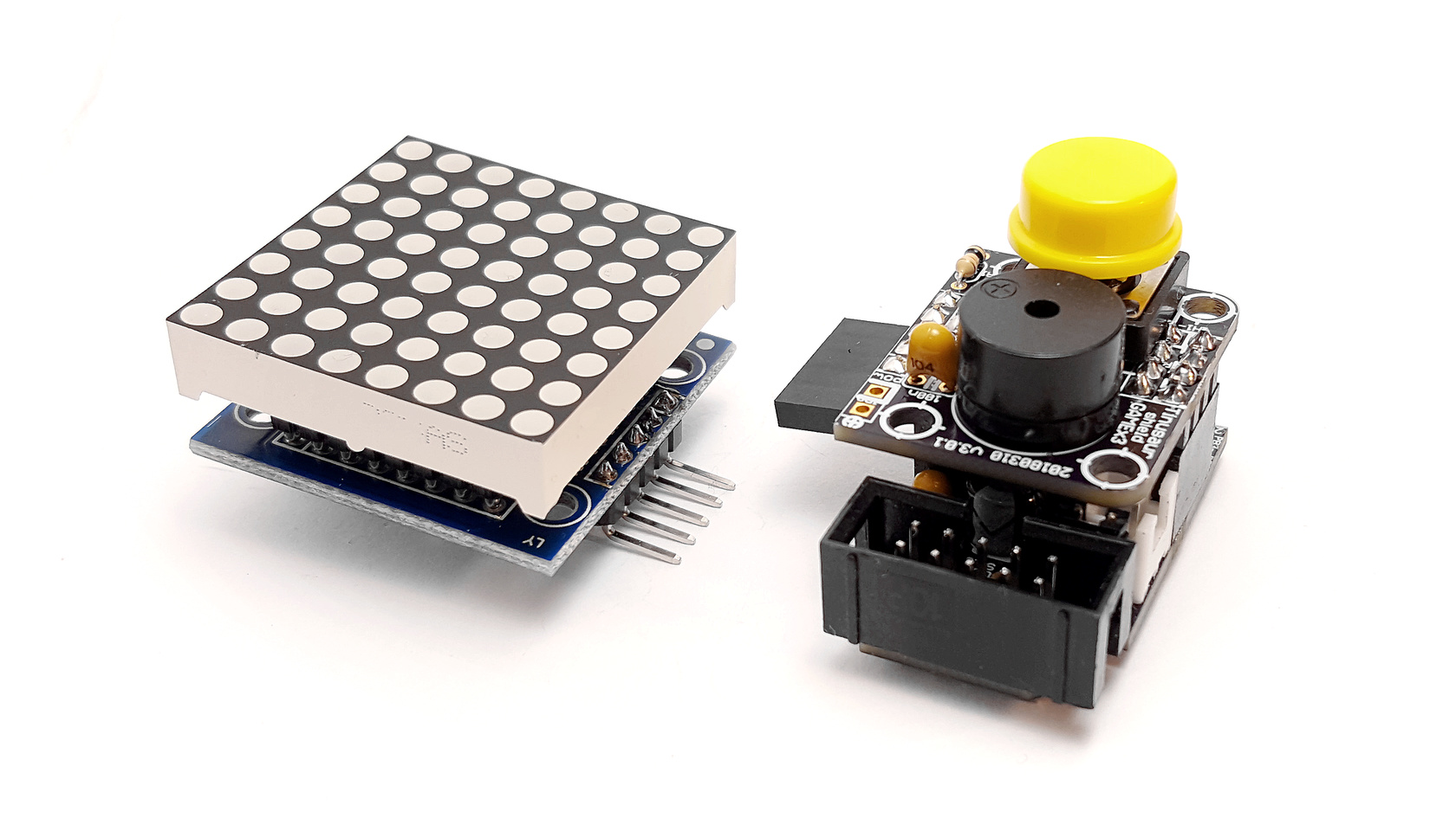
UPDATE 2022: The MAX7219LED8x8 library, now renamed to MAX7219tiny has now a new home at tinusaur.com/libraries/max7219tiny. Check also this MAX7219 & ATtiny85 tutorial to learn how the library works.

The MAX7219 controller manufactured by Maxim Integrated is a compact, serial input/output common-cathode display driver that could interface microcontrollers to 64 individual LEDs, 7-segment numeric LED displays of up to 8 digits, bar-graph displays, etc. Included on-chip are a BCD code-B decoder, multiplex scan circuitry, segment and digit drivers, and an 8×8 static RAM that stores each digit. 

The MAX7219 modules are very convenient to use with microcontrollers such as ATtiny85, or, in our case the Tinusaur Board.

The Hardware

The MAX7219 modules usually look like this:

MAX7219 Module LED Matrix 8x8
MAX7219 Module and LED Matrix 8×8

They have an input bus on one side and output bus on the other. This allows you to daisy chain 2 or more modules, i.e. one after another, to create more complicated setups.

The modules that we are using are capable of connecting in a chain using 5 small jumpers. See the picture below.

MAX7219 Module LED Matrix 8x8
2x MAX7219 Modules Connected

Pinout and Signals

MAX7219 module has 5 pins:

  • VCC – power (+)
  • GND – ground (-)
  • DIN – Data input
  • CS – Chip select
  • CLK – Clock

That means that we need 3 pins on the ATtiny85 microcontroller side to control the module. Those will be:

  • PB0 – connected to the CLK
  • PB1 – connected to the CS
  • PB2 – connected to the DIN

This is sufficient to connect to the MAX7219 module and program it.

The Protocol

Communicating with the MAX7219 is relatively easy – it uses a synchronous protocol which means that for every data bit we send there is a clock cycle that signifies the presence of that data bit.

MAX7219 Timing Diagram

In other words, we send 2 parallel sequences to bits – one for the clock and another for the data. This is what the software does.

The Software

The way this MAX7219 module works is this:

  • We write bytes to its internal register.
  • MAX7219 interprets the data.
  • MAX7219 controls the LEDs in the matrix.

That also means that we don’t have to circle through the array of LEDs all the time in order to light them up – the MAX7219 controller takes care of that. It could also manage the intensity of the LEDs.

So, to use the MAX7219 modules in a convenient way we need a library of functions to serve that purpose.

First, we need some basic functions in order to write to the MAX7219 registers.

  • Writing a byte to the MAX7219.
  • Writing a word (2 bytes) to the MAX7219.

The function that writes one byte to the controller looks like this:

void max7219_byte(uint8_t data) {
    for(uint8_t i = 8; i >= 1; i--) {
        PORTB &= ~(1 << MAX7219_CLK);   // Set CLK to LOW
        if (data & 0x80)                // Mask the MSB of the data
            PORTB |= (1 << MAX7219_DIN);    // Set DIN to HIGH
        else
            PORTB &= ~(1 << MAX7219_DIN);   // Set DIN to LOW
        PORTB |= (1 << MAX7219_CLK);        // Set CLK to HIGH
        data <<= 1;                     // Shift to the left
    }
}

Now that we can send bytes to the MAX7219 we can start sending commands. This is done by sending 2 byes – 1st for the address of the internal register and the 2nd for the data we’d like to send.

There is more than a dozen of register in the MAX7219 controller.

MAX7219 Registers and Commands

Sending a command, or a word, is basically sending 2 consecutive bytes. The function implementing that is very simple.

void max7219_word(uint8_t address, uint8_t data) {
    PORTB &= ~(1 << MAX7219_CS);    // Set CS to LOW
    max7219_byte(address);          // Sending the address
    max7219_byte(data);             // Sending the data
    PORTB |= (1 << MAX7219_CS);     // Set CS to HIGH
    PORTB &= ~(1 << MAX7219_CLK);   // Set CLK to LOW
}

It is important to note here the line where we bring the CS signal back to HIGH – this marks the end of the sequence – in this case, the end of the command. A similar technique is used when controlling more than one matrix connected in a chain.

Next step, before we start turning on and off the LEDs, is to initialize the MAX7219 controller. This is done by writing certain values to certain registers. For convenience, while coding it we could put the initialization sequence in an array.

uint8_t initseq[] = {
    0x09, 0x00, // Decode-Mode Register, 00 = No decode
    0x0a, 0x01, // Intensity Register, 0x00 .. 0x0f
    0x0b, 0x07, // Scan-Limit Register, 0x07 to show all lines
    0x0c, 0x01, // Shutdown Register, 0x01 = Normal Operation
    0x0f, 0x00, // Display-Test Register, 0x00 = Normal Operation
};

We just need to send the 5 commands above in a sequence as address/data pairs.

Next step – lighting up a row of LEDs.

This is very simple – we just write one command where 1st byte is the address (from 1 to 8) and the 2nd byte is the 8 bits representing the 8 LEDs in the row.

void max7219_row(uint8_t address, uint8_t data) {
    if (address >= 1 && address <= 8) max7219_word(address, data);
}

It is important to note that this will work for 1 matrix only. If we connect more matrices in a chain they will all show the same data. The reason for this is that after sending the command we bring the CS signal back to HIGH which causes all the MAX7219 controllers in the chain to latch and show whatever the last command was.

Testing

This is a simple testing program that lights up a LED on the first row (r=1) on the right-most position, then moves that on the left until it reaches the left-most position, then does the same on one row up (r=2) )until it reaches the top (r=8).

max7219_init();
for (;;) {
    for (uint8_t r = 1; r <= 8; r++) {
        uint8_t d = 1;
        for (uint8_t i = 9; i > 0; i--) {
            max7219_row(r, d);
            d = d << 1;
            _delay_ms(50);
        }
    }
}
MAX7219 Testing MAX7219LED8x8 Library
MAX7219 Testing

This testing code doesn’t do much but it demonstrates how to communicate with the MAX7219 controller.

The MAX7219LED8x8 Library

All of the functions mentioned above are part of the MAX7219LED8x8 library. Its source code is available at https://bitbucket.org/tinusaur/max7219led8x8.

The Tinusaur Shield GAMEx3

If you already have a Tinusaur Board we have the Shield GAMEx3 for it to connect a MAX7219 module easier to your ATtiny85 microcontroller.

Shield GAMEx3
Shield GAMEx3

The Gametinu Project

The Gametinu is a small game platform that you could build yourself using the Shield GAMEx3 and a few more parts and tools.

Gametinu
Gametinu

References

MAX7219 specification and datasheet:


This article is a rewritten version of another article from 2014:
MAX7219 driver for LED Matrix 8×8.


Tutorial 003: Making Sounds with Buzzer

Electromagnetic Buzzer

So far we’ve used a LED as output to produce light of different colors and intensity (Tutorial 001 and Tutorial 002) but we haven’t generated any sound yet.

In fact, that isn’t very difficult to do.

We will use a buzzer for output.

According to Wikipedia … the buzzer or beeper is an audio signaling device, which may be mechanical, electromechanical, or piezoelectric. Typical uses of buzzers and beepers include alarm devices, timers, and confirmation of user input such as a mouse click or keystroke.

Tinusaur Buzzer

We will use an electromechanical buzzer. When voltage is applied to it its membrane moves up (or down, depending on the particular device), and respectively when there is no voltage the membrane goes back to its normal position. Applying constantly changing voltage will generate audio waves perceived by us as a sound.

Let’s connect the buzzer to the PB2 of the ATtiny85 on the Tinusaur board.

The program should look very much like the one for blinking LED except that the delay between switching the port should be very short.

In the example below we have a delay 500 and since we’re using the _delay_us() function that means the delay is 500 uS (microseconds). That means the period of the signal will be 2 x 500 uS = 1000 uS (or 0.0001 sec.) and then the frequency is 1 / 0.0001 S = 10000. That means the sound will have a frequency of 10 KHz.

Here is the source code:

#include <stdint.h>
#include <avr/io.h>
#include <util/delay.h>
#define BUZZER_PORT     PB2     // Buzzer I/O Port
#define BUZZER_DELAY    500     // Delay for each tick
int main(void)
{
    DDRB |= (1 << BUZZER_PORT); // Set port as output
    while (1) {
        PORTB |= (1 << BUZZER_PORT);
        _delay_us(BUZZER_DELAY);
        PORTB &= ~(1 << BUZZER_PORT);
        _delay_us(BUZZER_DELAY);
    }
    return (0);
}

Full source code with more comments and the other necessary files such as Makefile is available at https://bitbucket.org/tinusaur/tutorials/src/default/tut003_buzzer/

Build the program:

$ make

Upload the code to the controller:

$ avrdude -c usbasp -p t85 -U flash:w:"main.hex":a

The buzzer should start making sounds immediately.

Let’s do some more experiments.

Let’s make the delay between the buzzer ticks change over time and see what sound it will produce.

This time instead of _delay_us() we will use the _delay_loop_2() function. According to the _delay_loop_2(int) documentation it produces 4 empty CPU cycles per iteration – in other words with parameter 100 it will produce a delay of 400 CPU cycles. That tells us that the maximum is 65536 x 4 = 262252 cycles. That, at 1MHz CPU clock, is approximately 262 mS (milliseconds) maximum delay, … or about 3.8 Hz minimum frequency – perfect for our experiments.

Below is the source code:

#include <stdint.h>
#include <avr/io.h>
#include <util/delay.h>
#define BUZZER_PORT     PB2     // Buzzer I/O Port
#define BUZZER_DELAY    200     // Delay for each tick
int main(void)
{
    DDRB |= (1 << BUZZER_PORT); // Set port as output
    int delay = 0;
    while (1) {
        if (delay < 1) delay = BUZZER_DELAY;
        PORTB |= (1 << BUZZER_PORT);
        _delay_loop_2(delay);
        PORTB &= ~(1 << BUZZER_PORT);
        _delay_loop_2(delay);
        delay--;
    }
    return (0);
}

After building and uploading this should start making sounds like a car alarm.

With similar techniques, a lot more complex sounds could be generated.

This post will eventually become Tutorial 003.

Tutorial 002: Fading LED x1

Another beginners tutorial is on the way – this time about a fading in and out LED.

This is simple tutorial that shows how to connect a LED to the ATtiny85 based Tinusaur board and write a program that makes the LED to fade in and out using PWM (pulse-width-modulation) technique.

PWM Diagram

Note: The code in this tutorial does not use the built-in PWM capabilities of the ATtiny microcontrollers, instead it uses direct bit manipulation since this an easier way to understand how it works. Another tutorial should cover the PWM functionality that is built into the microcontroller.

Tinusaur Board with LED

The Tinusaur board is a standard ATtiny breakout board so this could be applied to almost any other board that has ATtiny microcontroller on it. The code was tested to work with ATtiny13, ATtiny25, ATtiny45 and ATtiny85 but will probably work on any other ATtiny microcontrollers as well.

Please go to Tutorial 002: Fading LED x1 to see the full document.

You can also check the Tinusaur Board – Assembling Guide and the WinAVR – Setup Guide.

(UPDATED) Tutorial 001: Blinking LED

Tinusaur Tutorial 001 schematics

Our first tutorial Tutorial 001: Blinking LED (that’s the older one) was just updated and put under the Tutorials menu.

This is very simple tutorial that shows how to connect a LED to the Tinusaur board and write the “Hello World” of the microcontrollers – very simple program that makes a LED to blink.

Since the Tinusaur board is a very standard ATtiny breakout board this could be applied to almost any other board that has ATtiny microcontroller.

The code was tested to work with ATtiny13, ATtiny25, ATtiny45 and ATtiny85 but will probably work with other microcontrollers too.

Please go to the Tutorial 001: Blinking LED x1 page to see the full document.


Tutorial 001: Blinking LED

Tinusaur Tutorial 001: Blinking LED

UPDATE: New version of this tutorial is available on the Tutorial 001: Blinking LED x1 page.

Tinusaur Tutorial 001: Blinking LED

This is a very simple tutorial on how to make a LED blinking.

Since the Tinusaur board is a very standard ATtiny breakout board this could be applied to almost any such other board.

The code was tested to work with ATtiny13, ATtiny25, ATtiny45, and ATtiny85 but will probably work with other chips too.

We assume that the Tinusaur board is already assembled, successfully; connected through the ISP programmer to the computer; and development environment. It is not the subject of this tutorial how to assemble the board or how to setup a development environment.

The LED should be connected on pin 2 of the ATtiny – this is PB3 – through a resistor, and to the GND.

The LED, marked as D1, is just a standard light-emitting diode.

The resistor, marked as R1,  is 270 to 330 ohm.

The most important fragment of the code is this:

	while (1) {
		PORTB |= (1 << LED_PORT);
		_delay_ms(200);
		PORTB &= ~(1 << LED_PORT);
		_delay_ms(400);
	}

What it does is this:

  1. Start an infinite loop.
  2. Set the LED wire signal to “1” – that will make it to light.
  3. Wait a little – 200 milliseconds.
  4. Clear the LED wire signal to “0” – that will turn it off.
  5. Wait a little -400 milliseconds.
  6. Do it again.

Here is the entire source code:

/**
 * The Tinusaur Project
 *
 * Tutorial 001: Blinking LED
 *
 * file: main.c
 * created: 2014-01-04
 *
 **/

#include <avr/io.h>
#include <util/delay.h>

// ====================================
//                ATtiny
//               25/45/85
//              +--------+
//            --+ o  Vcc +------------
//  LED - PB3 --+        +--
//            --+        +--
//  ------------+ GND    +--
//              +--------+
// ====================================

// Define the I/O port to be used for the LED.
// This a number between 0 and 7 that tells which bit to use.
#define LED_PORT PB3

int main(void) {

	// Set the LED port number as output.
	// The DDRB is the data direction for port B.
	// This ...
	//  - shifts the "1" on left to the desired position and ...
	//  - does bitwise "OR" with the value in the port register.
	DDRB |= (1 << LED_PORT);

	// Start infinite loop.
	// (this is how most programs work)
	while (1) {

		// Set the LED bit to "1" - LED will be "on".
		PORTB |= (1 << LED_PORT);

		// Wait a little.
		// The delay function simply does N-number of "empty" loops.
		_delay_ms(200);

		// Set the LED bit to "0" - LED will be "off".
		PORTB &= ~(1 << LED_PORT);

		// Wait a little.
		_delay_ms(400);

		// Do it again ...
	}

	// Return the mandatory for the "main" function value.
	return (0);
}

Copy the code above to your “main.c” file.

The source code could be also found on Bitbucket at this address: https://bitbucket.org/tinusaur/tutorials/src/1f61873ae382/tut001/src/main.c.

The circuit schematics, even though very simple, was drawn on 123d.circuits.io and it is available at this address: http://123d.circuits.io/circuits/76781.