Updated SSD1306xLED library, fixes, compatibility with SSD1315 and more

SSD1306xLED Testing

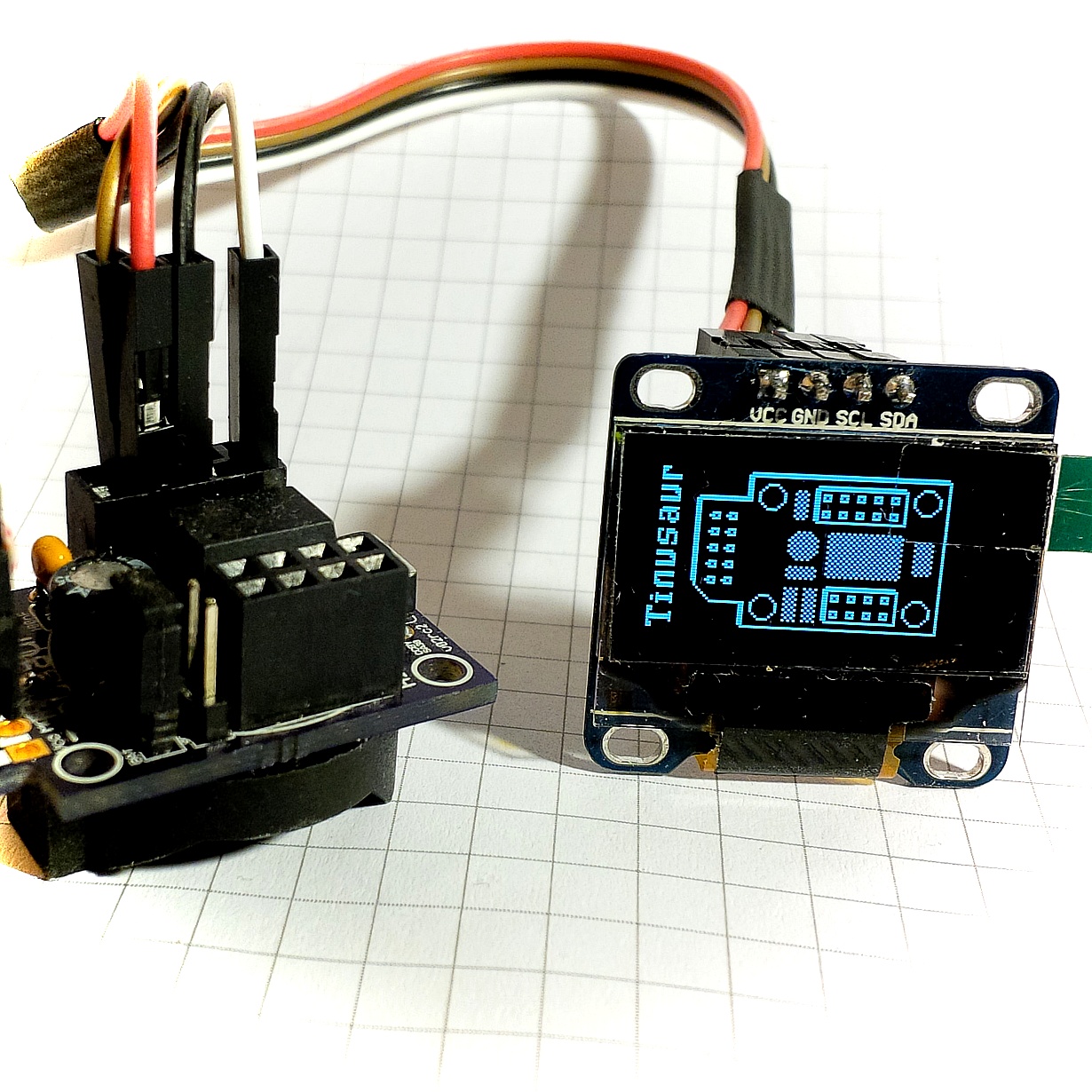
Our SSD1306xLED library works well with the SSD1306 displays, it is small as binary code and is very fast.

But, there was a problem …

Several months ago we ordered some displays from the Far East and we expected them to work just fine. Unfortunately, they did not. And the problem was not in our library but with the chips. Instead of SSD1306, it seems they put the not that well known SSD1315 OLED display controller. We found that out by looking closely at the PCB, beneath the LCD glass plate.

ssd1306xled testing
SSD1315 OLED display controller

The testing script was producing the result shown in the picture. Note the bottom lines – they were not redrawn, or not always, at least.

On another display that we’ve got earlier, a few years ago, and that was using the SSD1306 controller the picture was looking good.

SSD1306xLED Testing
SSD1306 OLED display controller

Apparently, the problem was with the display controller. Further experiments proved that.

What made it worse for us was that we’ve discovered that from about a hundred display modules we’ve ordered recently half seemed not compatible with our code. We couldn’t even figure out what exactly was the OLED controller on those modules –
SSD1306 as stated in the description where we bought them, or the SSD1315 looking at the testing scripts results. So, we decided to just fix the problem for both kinds of chips. Easy to say it than to do it.

First attempt

2 months ago. We played with the timing and the speed of the data sent to the modules. Tried a few other things, like reordering the commands sent while drawing. We even moved some of the I2C specific code to a separate library to isolate the potential problems and try to fix the issue. No luck.

Second attempt

2 days ago. We decided to re-do the initialization sequence for the OLED controller. These are the commands that we send to the chip before we start drawing things on the display. We read, again, the Solomon Systech PDF file about the SSD1306 controller – the so-called datasheet. There was a half-baked algorithm of how to initialize the chip. Also, looked at several other libraries to see how they do it. Actually, the “Adafruit_SSD1306.cpp” was a really good example so we used some know-how from it.

Wrote the code. Tested it. And, it worked!

Done!

SSD1306xLED Testing
SSD1306xLED Testing

Some optimizations

There were a couple of TO-DO’s in the source code for the optimization of multiplication by a constant. That could be easily converted to a combination of 1 or more left-bitwise-shift and additions.

void ssd1306tx_char(char ch) {
  uint8_t c = ch - 32; // Convert ASCII code to font data index.
  ssd1306_start_data();
  for (uint8_t i = 0; i < 6; i++) {
    ssd1306_data_byte(pgm_read_byte(&ssd1306tx_font_src[c * 6 + i]));
  }
  ssd1306_stop();
}

We combined the c = ch – 32 and the c * 6 + i and optimized the entire expression.

void ssd1306tx_char(char ch) {
  uint16_t j = (ch << 2) + (ch << 1) - 192;
  ssd1306_start_data();
  for (uint8_t i = 0; i < 6; i++) {
    ssd1306_data_byte(pgm_read_byte(&ssd1306tx_font_src[j + i]));
  }
  ssd1306_stop();
}

That saved us about 30 bytes of binary code and it is probably a bit faster than the multiplication with a subroutine.

We did something similar for the void ssd1306tx_stringxy(const uint8_t *fron_src, uint8_t x, uint8_t y, const char s[]); function but without the left-bitwise-shift as the compiler optimizes the very well the multiplication with numbers that are powers of 2, i.e. 2, 4, 8, etc. In our case – 16. That saved us another 20 bytes of binary code and probably gained some speed.

So, we saved about 50 bytes of machine code and gained some speed. That might not look that much but for a microcontroller with 4096 bytes for code and 1 or 8 MHz CPU that’s about 1.2% less memory usage. And, our library is now a bit faster.

Resources

There are more functions in the SSD1306xLED library such as for printing text and numbers on the screen and drawing images but that will be subject of another article.

The official page of the library (will be):
/software/libraries/ssd1306xled/

Source code is available at:
https://bitbucket.org/tinusaur/ssd1306xled/src

Interfacing a MAX7219 Driven LED Matrix with ATtiny85

LED Matrix 8x8 MAX7219 Assembling

UPDATE 2022: The MAX7219LED8x8 library, now renamed to MAX7219tiny has now a new home at tinusaur.com/libraries/max7219tiny. Check also this MAX7219 & ATtiny85 tutorial to learn how the library works.

The MAX7219 controller manufactured by Maxim Integrated is a compact, serial input/output common-cathode display driver that could interface microcontrollers to 64 individual LEDs, 7-segment numeric LED displays of up to 8 digits, bar-graph displays, etc. Included on-chip are a BCD code-B decoder, multiplex scan circuitry, segment and digit drivers, and an 8×8 static RAM that stores each digit. 

The MAX7219 modules are very convenient to use with microcontrollers such as ATtiny85, or, in our case the Tinusaur Board.

The Hardware

The MAX7219 modules usually look like this:

MAX7219 Module LED Matrix 8x8
MAX7219 Module and LED Matrix 8×8

They have an input bus on one side and output bus on the other. This allows you to daisy chain 2 or more modules, i.e. one after another, to create more complicated setups.

The modules that we are using are capable of connecting in a chain using 5 small jumpers. See the picture below.

MAX7219 Module LED Matrix 8x8
2x MAX7219 Modules Connected

Pinout and Signals

MAX7219 module has 5 pins:

  • VCC – power (+)
  • GND – ground (-)
  • DIN – Data input
  • CS – Chip select
  • CLK – Clock

That means that we need 3 pins on the ATtiny85 microcontroller side to control the module. Those will be:

  • PB0 – connected to the CLK
  • PB1 – connected to the CS
  • PB2 – connected to the DIN

This is sufficient to connect to the MAX7219 module and program it.

The Protocol

Communicating with the MAX7219 is relatively easy – it uses a synchronous protocol which means that for every data bit we send there is a clock cycle that signifies the presence of that data bit.

MAX7219 Timing Diagram

In other words, we send 2 parallel sequences to bits – one for the clock and another for the data. This is what the software does.

The Software

The way this MAX7219 module works is this:

  • We write bytes to its internal register.
  • MAX7219 interprets the data.
  • MAX7219 controls the LEDs in the matrix.

That also means that we don’t have to circle through the array of LEDs all the time in order to light them up – the MAX7219 controller takes care of that. It could also manage the intensity of the LEDs.

So, to use the MAX7219 modules in a convenient way we need a library of functions to serve that purpose.

First, we need some basic functions in order to write to the MAX7219 registers.

  • Writing a byte to the MAX7219.
  • Writing a word (2 bytes) to the MAX7219.

The function that writes one byte to the controller looks like this:

void max7219_byte(uint8_t data) {
    for(uint8_t i = 8; i >= 1; i--) {
        PORTB &= ~(1 << MAX7219_CLK);   // Set CLK to LOW
        if (data & 0x80)                // Mask the MSB of the data
            PORTB |= (1 << MAX7219_DIN);    // Set DIN to HIGH
        else
            PORTB &= ~(1 << MAX7219_DIN);   // Set DIN to LOW
        PORTB |= (1 << MAX7219_CLK);        // Set CLK to HIGH
        data <<= 1;                     // Shift to the left
    }
}

Now that we can send bytes to the MAX7219 we can start sending commands. This is done by sending 2 byes – 1st for the address of the internal register and the 2nd for the data we’d like to send.

There is more than a dozen of register in the MAX7219 controller.

MAX7219 Registers and Commands

Sending a command, or a word, is basically sending 2 consecutive bytes. The function implementing that is very simple.

void max7219_word(uint8_t address, uint8_t data) {
    PORTB &= ~(1 << MAX7219_CS);    // Set CS to LOW
    max7219_byte(address);          // Sending the address
    max7219_byte(data);             // Sending the data
    PORTB |= (1 << MAX7219_CS);     // Set CS to HIGH
    PORTB &= ~(1 << MAX7219_CLK);   // Set CLK to LOW
}

It is important to note here the line where we bring the CS signal back to HIGH – this marks the end of the sequence – in this case, the end of the command. A similar technique is used when controlling more than one matrix connected in a chain.

Next step, before we start turning on and off the LEDs, is to initialize the MAX7219 controller. This is done by writing certain values to certain registers. For convenience, while coding it we could put the initialization sequence in an array.

uint8_t initseq[] = {
    0x09, 0x00, // Decode-Mode Register, 00 = No decode
    0x0a, 0x01, // Intensity Register, 0x00 .. 0x0f
    0x0b, 0x07, // Scan-Limit Register, 0x07 to show all lines
    0x0c, 0x01, // Shutdown Register, 0x01 = Normal Operation
    0x0f, 0x00, // Display-Test Register, 0x00 = Normal Operation
};

We just need to send the 5 commands above in a sequence as address/data pairs.

Next step – lighting up a row of LEDs.

This is very simple – we just write one command where 1st byte is the address (from 1 to 8) and the 2nd byte is the 8 bits representing the 8 LEDs in the row.

void max7219_row(uint8_t address, uint8_t data) {
    if (address >= 1 && address <= 8) max7219_word(address, data);
}

It is important to note that this will work for 1 matrix only. If we connect more matrices in a chain they will all show the same data. The reason for this is that after sending the command we bring the CS signal back to HIGH which causes all the MAX7219 controllers in the chain to latch and show whatever the last command was.

Testing

This is a simple testing program that lights up a LED on the first row (r=1) on the right-most position, then moves that on the left until it reaches the left-most position, then does the same on one row up (r=2) )until it reaches the top (r=8).

max7219_init();
for (;;) {
    for (uint8_t r = 1; r <= 8; r++) {
        uint8_t d = 1;
        for (uint8_t i = 9; i > 0; i--) {
            max7219_row(r, d);
            d = d << 1;
            _delay_ms(50);
        }
    }
}
MAX7219 Testing MAX7219LED8x8 Library
MAX7219 Testing

This testing code doesn’t do much but it demonstrates how to communicate with the MAX7219 controller.

The MAX7219LED8x8 Library

All of the functions mentioned above are part of the MAX7219LED8x8 library. Its source code is available at https://bitbucket.org/tinusaur/max7219led8x8.

The Tinusaur Shield GAMEx3

If you already have a Tinusaur Board we have the Shield GAMEx3 for it to connect a MAX7219 module easier to your ATtiny85 microcontroller.

Shield GAMEx3
Shield GAMEx3

The Gametinu Project

The Gametinu is a small game platform that you could build yourself using the Shield GAMEx3 and a few more parts and tools.

Gametinu
Gametinu

References

MAX7219 specification and datasheet:


This article is a rewritten version of another article from 2014:
MAX7219 driver for LED Matrix 8×8.


Working with DS1307 Real-time Clock and ATtiny85 using USITWIX Library

DS1307 Serial Real-Time Clock USITWIX Tinusaur.

Working with the DS1307 Serial Real-Time Clock using the USITWIX library for I2C / TWI on Atmel ATtiny85 / Tinusaur.

Let’s see how can we work with the DS1307 serial real-time clock using the USITWIX library for I2C / TWI on Atmel ATtiny85 / Tinusaur.

Bellow is the testing setup.

NOTE: We need the USB-to-Serial just for debugging – it isn’t essential part of the setup.

DS1307 Serial Real-Time Clock USITWIX Tinusaur.

There is no library yet to do that but with in the testing code there are few functions that could do the job.

Here is brief a description of the functions:

  • uint8_t ds1307_read_reg8(uint8_t reg_addr) – reads one byte of data from the specified register.
  • uint8_t ds1307_write_reg8(uint8_t reg_addr, uint8_t reg_data) – write one byte of data to the specified register.
  • uint8_t ds1307_init(void) – initializes the circuit by writing specific data into the registers.
  • uint8_t ds1307_setdatetime(uint16_t year, uint8_t month, uint8_t date, uint8_t weekday, uint8_t hour, uint8_t min, uint8_t sec) – sets date and time.
  • uint8_t ds1307_adjust(void) – this is helper function – it sets the date & time to a specific value – let’s not forget that a brand new circuit does not have correct date and time set.

DS1307 Serial Real-Time Clock ModuleThere are 2 additional functions that are used to convert data byte to and from BCD format.

  • static uint8_t bcd2bin (uint8_t val)
  • static uint8_t bin2bcd (uint8_t val)

This is direct link to the source code of the testing program:
https://bitbucket.org/tinusaur/ds1307tiny/src/default/ds1307tiny_test1/main.c

Source code available at: https://bitbucket.org/tinusaur/ds1307tiny

More information about the library will be available at its own page: DS1307tiny

Working with BMP180 Pressure Sensor and ATtiny85 using USITWIX Library

USITWIX – Using USI as TWI / I2C

In our previous post “USITWIX – Using UART as TWI / I2C” we looked at the USITWIX library that implements TWI / I2C communication between а  ATtiny85 micro-controller and peripherals. Let’s see now how we can use that library to work with the BOSCH BMP180 atmospheric pressure sensor and a ATtiny85/Tinusaur boards.

The BMP180tiny Library

So, we wrote a simple library (called it BMP180tiny) that uses USITWIX to read and write from/to BMP180 registers, retrieve the measurements, do some additional calculations and produce result suitable for use in an application.

Setup

Here’s the setup:

BMP180 with Tinusaur ATtiny85 USITWIX

NOTE: We need the USB-to-Serial just for debugging – it isn’t essential part of the setup.

Here is a short fragment of initialization code

uint8_t bmp180_result;
if ((bmp180_result = bmp180_init()) != BMP180_RESULT_SUCCESS)
{
return -1;
}

And here is now to use the functions …

// Read raw temperature
uint16_t temp_rawdata = bmp180_read_temp_raw();

uint16_t temp_10x = bmp180_read_temp10x();
// temp_10x holds the result dC, i.e. 123 means 12.3 Celsius

// Read raw pressure
int32_t pres_rawdata = bmp180_read_pres_raw();

// Read pressure
int32_t pres = bmp180_read_pres();
int16_t pres_hpa = pres / 100;
// pres_hpa holds the result in hPa (hectopascals)

// Read altitude
int32_t alt_x = bmp180_read_alt_x();
int16_t alt_dm = alt_x / 100;
// alt_dm holds the result in dm (decimeters)

The debugging output would look something like this …

t:raw=28622; t(dC)=253; p:raw/hi=5; p:raw/lo=4940; p(Pa)/hi=1; p(Pa)/lo=33948; p(hPa)=994; a/lo=24222; a(dm)=1552;
t:raw=28624; t(dC)=253; p:raw/hi=5; p:raw/lo=4964; p(Pa)/hi=1; p(Pa)/lo=33933; p(hPa)=994; a/lo=24307; a(dm)=1553;
t:raw=28623; t(dC)=253; p:raw/hi=5; p:raw/lo=4951; p(Pa)/hi=1; p(Pa)/lo=33939; p(hPa)=994; a/lo=22619; a(dm)=1536;
t:raw=28624; t(dC)=253; p:raw/hi=5; p:raw/lo=4942; p(Pa)/hi=1; p(Pa)/lo=33940; p(hPa)=994; a/lo=24560; a(dm)=1556;

NOTE: This is generated using OWOWOD library and hardware (not required by the library itself to work)

References

The source code is available at https://bitbucket.org/tinusaur/bmp180tiny.
— The library is in the “bmp180tiny” folder.
— A sample code could found in the “bmp180tiny_test1” folder.

The page about BMP180tiny and articles about BMP180tiny.

The page about USITWIX and articles about USITWIX.

New Library: USITWIX – Using USI as TWI / I2C

Attiny85 Tinusaur USI TWI I2C BMP180 Variometer

As we know, there’s no I²C on ATtiny85, not even the TWI (Two Wire Interface, which is basically I2C with a different name) that some other Atmel chips have, so I had to write my own that takes advantage on the built-in USI unit. This library is called USITWIX and will be presented in this blog post.

Of course, I used other people’s work write mine and they’re references in the source code.

The primary source is the Atmel application note AVR312: Using the USI module as a I2C slave that explains how to use the  built-in USI unit as I2C slave.

The source code is already available at https://bitbucket.org/tinusaur/usitwix.

Some important code fragments

Although the TWI and I2C is a synchronous communication protocol it still requires precise timing.

In the code there are few places where some fixed time intervals are specified and this is in the usitwim.h file:

#define T2_TWI 5 // >4,7us
#define T4_TWI 4 // >4,0us

These may need to be adjusted if the CPU runs at a frequency different than default 1 MHz.

Using the USITWIX library

Paragliding

The BMP180TINY is another library for working with the BOSCH BMP180 atmospheric pressure sensor.The source code is available at https://bitbucket.org/tinusaur/bmp180tiny along with some samples.

There is also a Variometer project that uses those libraries to produce audible measurements of the changes in the altitude by measuring the atmospheric pressure and taking into account the temperature. Such tools, or instruments, are often used by paragliders.

Video here:
https://www.youtube.com/watch?v=6JTnYuJGo4w

References

Here are some references to sources that I used while working on this project.

AVR312: Using the USI module as a I2C slave
http://www.atmel.com/Images/doc2560.pdf
C-code driver for TWI slave, with transmit and receive buffers; Compatible with I2C protocol; Interrupt driven, detection and transmission/reception; Wake up from all sleep mode, including Power Down.

TINY USI Interface in I2C mode and the AVR312 Appnote
http://www.aca-vogel.de/TINYUSII2C_AVR312/APN_TINYUSI_I2C.html
What’s wrong with the AVR Appnote?

ATTiny USI I2C Introduction – A powerful, fast, and convenient communication interface for your ATTiny projects!
http://www.instructables.com/id/ATTiny-USI-I2C-The-detailed-in-depth-and-infor/
I2C, it’s a standard that’s been around for around 20 years and has found uses in nearly every corner of the electronics universe. It’s an incredibly useful technology for us microcontroller hobbyists but can seem daunting for new users. This tutorial will solve that problem, first by reviewing what I2C is and how it works, then by going in-depth on how to implement I2C in Atmel’s ATTiny USI (Universal Serial Interface) hardware.

I2C Bus for ATtiny and ATmega
http://www.instructables.com/id/I2C_Bus_for_ATtiny_and_ATmega/
This two wire interface is formally known as the Inter-Integrated Circuit bus, or just the I2C bus and was invented by NXP when it was still Philips Semiconductors. If you’re reading this Instructable then you’ve probably heard of the I2C bus and may even have used it on a PIC or other microcontroller. While conceptually very simple, and supported by hardware resources on the AVRs, software drivers are still necessary to use the I2C bus. Atmel provides Application Notes (see the Resources later in this Instructable), but these are incomplete and don’t show any examples beyond communicating with another AVR device.

The OWOWOD Library

OWOWOD is One Wire / One Way Output for Debugging library. It allows you to output text from the Tinusaur (ATtiny85 microcontroller or other similar), though USB-to-Serial or TTL converter (based on PL2303, CH340G or similar) and to the computer screen using COM port monitoring tool.

Why one would need something like that?

It would’ve been nice if it was possible to write something li this …

debugging_print("working, x=%i", x);

… and see the output on a computer. Great for debugging and other things.

Unfortunately ,there is no easy way of doing that – in fact not possible with the standard tools used to work with the ATtiny85. The problem is this: (1) those micro-controllers have too few I/O ports; and (2) most of the programmers (ex.: USBasp) do not offer that kind of communication between the micro-controller and the computer, i.e. there is no 2-way communication.

USB to Serial TTL

There are some solution and the OWOWOD library is just one of them. It uses an additional hardware component – USB-to-Serial converter also known as USB TTL Converter. They are very inexpensive, easy to find and work with.

The OWOWOD Library could do that.

Tinusaur connected to USB-to-Serial PL2303 using OWOWOD

For this to work we need …

  • Micro-controller
  • USB-to-Serial converter
  • Computer

The Library works like this …

  • When you use a library function like owowod_print_char(‘U’) it will start sending sending the bits of the ‘U’ byte (hex: 0x55, bin: 01010101) in series, i.e. one bit after another, through one of the microcontroller pins – for instance PB3.
  • At the other end of the wire there is USB-to-Serial converter that will take the individual 01010101 bits and re-compose them back into one byte as 0x55.
  • Then the USB-to-Serial converter will send that ‘U’ byte (0x55) to the computer USB port.
  • The computer sees the USB-to-Serial as a Serial COM Port port, so it reads that ‘U’ byte.
  • Using another program on the computer we get that ‘U’ byte and show it on the screen.

It works similarly for whole strings and other data.

Let’s take a look at some usage examples:

#include <stdlib.h>
#include <avr/io.h>
#define OWOWOD_PORT PB3
#include "../owowod/owowod.h"
int main(void) {
    owowod_init();
    owowod_print_char('U');
    owowod_print_string("Hello!\r\n");
    owowod_print_numdec(1);
    owowod_print_numdecp(2);
    owowod_print_numdecu(123);
    owowod_print_numdecup(456);
    return 0;
}

Always initialize with owowod_init() function.

You can print char, string but also decimal signed and unsigned integer numbers.

The decimal numbers are 16-bit integers.

The owowod_print_numdecp() and owowod_print_numdecup() functions print left padded numbers – that means there will be some spaces on the left as if the numbers are right aligned. Like this …

    12
   345
 67890
    -2
   -34
-56789

Because this would be used for debugging in most of the cases there are some helpful definitions for that purpose in the “debugging.h” file.

Here is an example of how to use it …

#define F_CPU 1000000UL
#include <stdint.h>
#include <avr/io.h>
#define OWOWOD_PORT PB3
#include "../owowod/owowod.h"
#include "../owowod/debugging.h"
int main(void) {
    DEBUGGING_INIT();
    DEBUGGING_NUMDEC(-123);
    DEBUGGING_NUMDECP(-4567);
    DEBUGGING_NUMDECU(123);
    DEBUGGING_NUMDECUP(4567);
    DEBUGGING_STRING("Hello!");
    DEBUGGING_STRINGLN("Hi!");
    DEBUGGING_VAR("X", 1);
    DEBUGGING_VARU("Y", 23);
    DEBUGGING_ERROR(4, "Connect");
    return 0;
}

DEBUGGING_STRINGLN adds CRLF new line at the end.

DEBUGGING_VAR and DEBUGGING_VARU print variable name and then the value.

DEBUGGING_ERROR prints the error code then the message.

hercules setup serial

To see the results we need a program that will run on a computer and show on the screen the information that comes through the serial port. There are many programs that could do that. One particularly simple to use is the Hercules Setup utility by HW group – it is just one EXE file that you run – that’s it.

The OWOWOD has its own page, it is at:
/projects/owowod/

This library was developed with and tested on the following microcontrollers: ATtiny85, ATtiny45, ATtiny25 but should also work on other tinyAVR chips.

The library was tested to work with following USB-to-Serial converters: PL2303, CH340G.

Source code is available at https://bitbucket.org/tinusaur/owowod.

References

There are many project in the Internet that solve the same or similar problems and this article http://www.ernstc.dk/arduino/tinycom.html that points to some of them:

On eBay: USB to Serial TTL converter – to transfer the debugging output from the ATtiny micro-controller to the computer.

Here are links to some of the posts related to this library:

Printing Decimal Numbers on SSD1306 OLED Display Using the SSD1306xLED Library

Tinusaur SSD1306XLED SSD1306 OLED Llibary

UPDATE: Please, check the most recent post about this library at /tag/ssd1306xled

After playing for awhile with that SSD1306 OLED display I decided to add few more things to the SSD1306xLED library and the ability to print numbers seamed to be an important one.

Tinusaur SSD1306xLED ATtiny85 SSD1306 OLDEThere is already a function in the library that outputs strings so I needed only the conversion from int to a decimal string. So I used another function usint2decascii that I previously wrote for another project OWOWOD which code, in turn, I borrowed from a third project LCDDDD – an LCD Direct Drawing Driver for PCD8544 based displays such as Nokia 3310 LCD. The weird LCDDDD name comes from the fact that it outputs the data directly to the LCD instead of storing it into a buffer first and then periodically outputting it to the LCD – this is unlike most of the popular LCD drivers.

Here is the main function definition …

uint8_t usint2decascii(uint16_t num, char* buffer)

The function requires a small buffer to store the result. Since the largest number is 65535 – that is 0xFFFF in hex, 5+1 bytes are needed for that buffer.

For convenience, there are 2 functions for direct printing of numbers. Below is their implementation – it’s very simple:

#define USINT2DECASCII_MAX_DIGITS 5

char ssd1306_numdec_buffer[USINT2DECASCII_MAX_DIGITS + 1];

void ssd1306_numdec_font6x8(uint16_t num) {
  ssd1306_numdec_buffer[USINT2DECASCII_MAX_DIGITS] = '&#092;&#048;';
  uint8_t digits = usint2decascii(num, ssd1306_numdec_buffer);
  ssd1306_string_font6x8(ssd1306_numdec_buffer + digits);
}

void ssd1306_numdecp_font6x8(uint16_t num) {
  ssd1306_numdec_buffer[USINT2DECASCII_MAX_DIGITS] = '&#092;&#048;';
  usint2decascii(num, ssd1306_numdec_buffer);
  ssd1306_string_font6x8(ssd1306_numdec_buffer);
}

The ssd1306_numdec_font6x8 only prints the number while ssd1306_numdecp_font6x8 prints numbers the same way but right-aligned and 5-digit padded.

Printing numbers is as simple as this …

  ssd1306_setpos(20, 4);
  ssd1306_numdecp_font6x8(12345);

Here is a little more complicated example …

ssd1306_setpos(40, 3);
ssd1306_string_font6x8("a=");
ssd1306_numdecp_font6x8(0xFA32); // dec: 64050
ssd1306_setpos(40, 4);
ssd1306_string_font6x8("b=");
ssd1306_numdecp_font6x8(0x05CD); // dec: 1485

ssd1306xled sample screen

It prints “a=”, “b=” and then their values. Both numbers are right-aligned and left-padded with up to 4 spaces.

The latest test program in SSD1306xLED includes examples of how to use the ssd1306_numdec_font6x8 and the ssd1306_numdecp_font6x8 functions.

The SSD1306xLED library is at SSD1306xLED page.

The source code of the SSD1306xLED is available at https://bitbucket.org/tinusaur/ssd1306xled

The source code of the TinyAVRLib is available at https://bitbucket.org/tinusaur/tinyavrlib

UPDATE: MAX7219LED8x8 uses simple scheduler

UPDATE 2022: The MAX7219LED8x8 library, now renamed to MAX7219tiny has now a new home at tinusaur.com/libraries/max7219tiny. Check also this MAX7219 & ATtiny85 tutorial to learn how the library works.

max7219 LED 8x8 Tinusaur ATtiny85

The MAX7219LED8x8 library uses now a simple scheduler to automate the task of outputting the buffer to the LED 8×8 matrix. This is not like a real task scheduler (in a real operating system) but it uses the ATtiny85 microcontroller‘s timer and its interrupt to do certain things at regular intervals.

So this is how I’ve got the idea …

While I was working on some code that uses the MAX7219LED8x8 library I figured out that the task of writing the content of the memory buffer to the MAX7219 could be automated by hooking some code to the ATtiny85 timer.

The modification and additions could be broken down into 2 parts:

First, the scheduling part initializes the ATtiny85 timer, starts it, and handles the hardware interrupt.

Second, the MAX7219LED8x8 library functions for setting/clearing pixels and outputting the buffer that now should work with the scheduler.

There are only 3 functions to handle the scheduling:

void scheduler_init(void);
void scheduler_start(uint8_t max);
void scheduler_userfunc(void);

The scheduler_init function initializes the timer and the scheduler_start starts the timer task to be executed on equal intervals defined by the max parameter.

The scheduler_userfunc function should be implemented in the application so it could be called at regular intervals.

There is no “stop” function at the moment since it was not needed in this particular case.

The code for initializing and starting the ATtiny85 timer is very simple:

void scheduler_init(void) {
    // Setup Timer
    TCCR0A |= (1 << WGM01); // set timer in CTC mode
    TIMSK |= (1 << OCIE0A); // set Bit 4 – OCIE0A:
    // ... Timer/Counter0 Output Compare Match A Interrupt Enable
}

void scheduler_start(uint8_t max) {
    // IMPORTANT: Requires TIMER0_COMPA_vect to be setup.
    sei(); //  Enable global interrupts
    OCR0A = max;    // set value for OCR0A - Output Compare Register A
    // Prescale and start timer: 1/1024-th
    TCCR0B |= (1 << CS02) | (0 << CS01) | (1 << CS00);
}

// Define interrupt vector
ISR(TIMER0_COMPA_vect)
{
    scheduler_userfunc();
    // Note: No need to clear flags in TIFR - done automatically
}

On the MAX7219LED8x8 side there are only 3 functions currently implemented:

void max7219s_init(void);
void max7219s_start(void);
void max7219s_buffer_out(void);

The max7219s_buffer_out function is the one called within the scheduler_userfunc timer handler.

Everything else remains the same – we use MAX7219_buffer_set(x, y) to set pixel and MAX7219_buffer_clr(x, y) to clear pixel.

What could be improved and optimized: output the buffer only when it is changed.

More information is available on the MAX7219LED8x8 library page.

The source code of the MAX7219LED8x8 library, the scheduler, and everything else are available at https://bitbucket.org/tinusaur/max7219led8x8.