The Blocktinu App for Windows version 1.2.1 is out
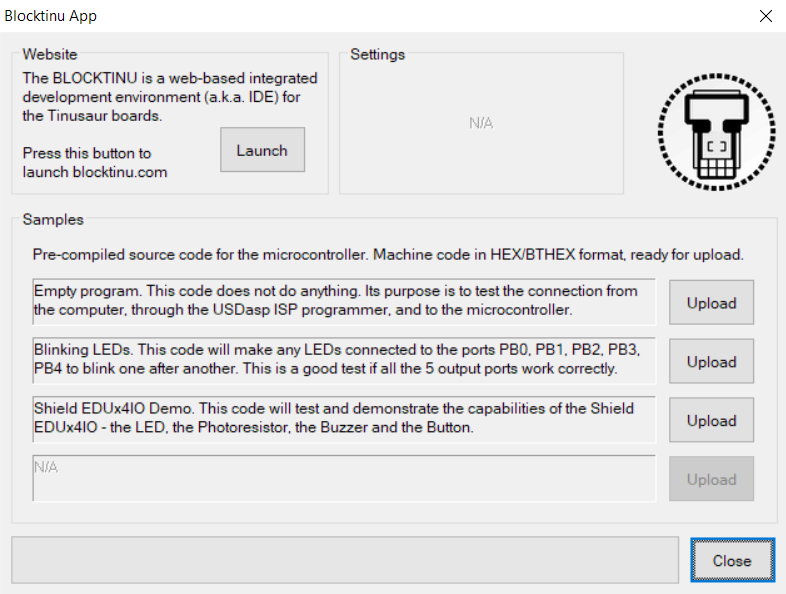
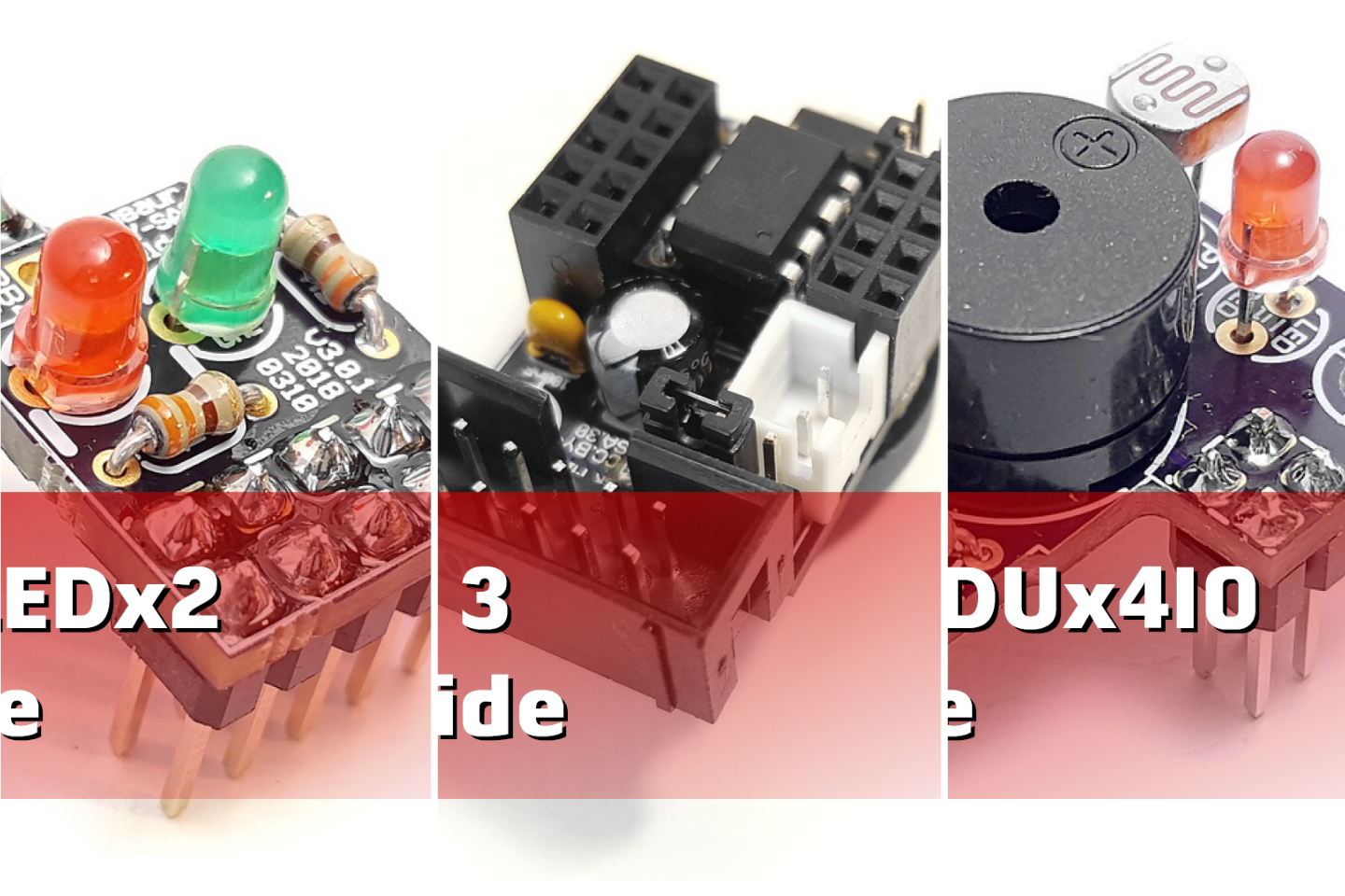
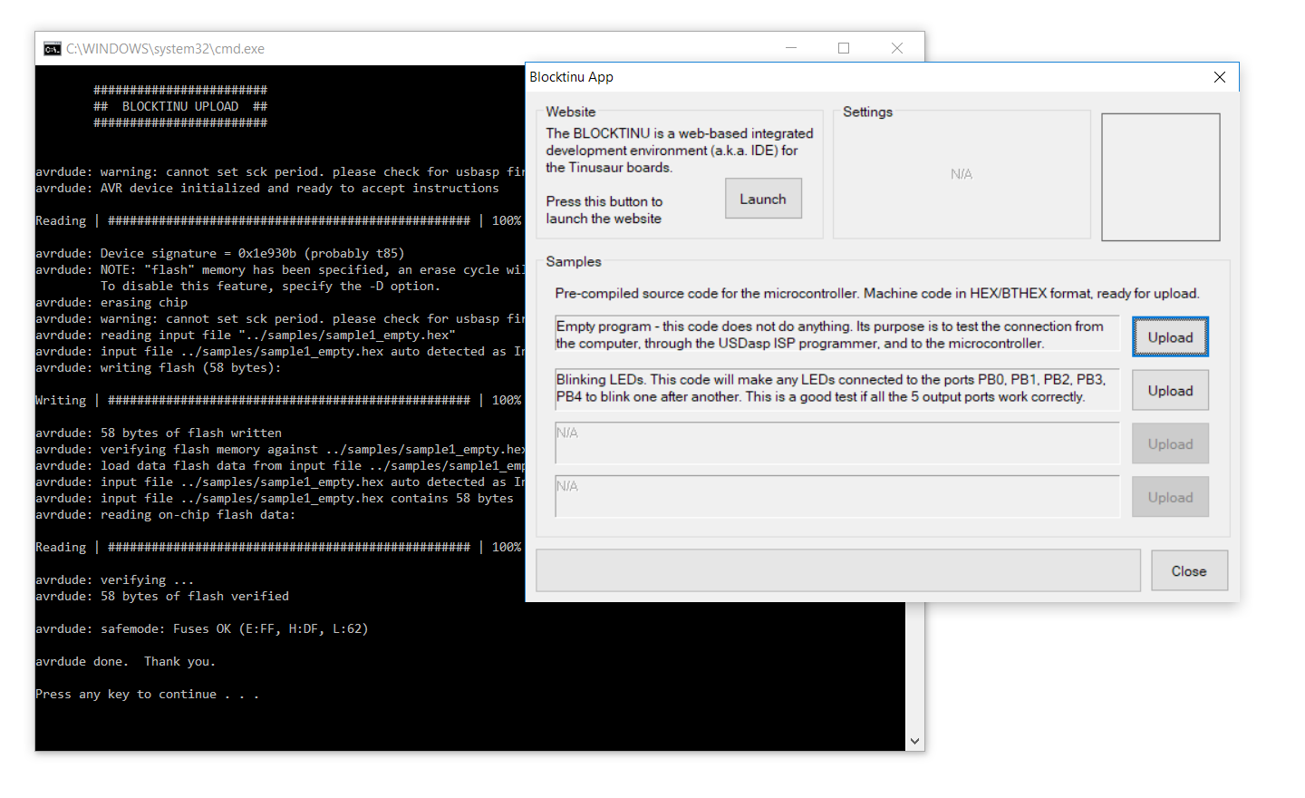
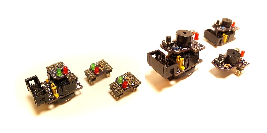
We have just deployed a new version of the Blocktinu Windows application. It is available for download from BLOCKTINU.com/downloads website. WHAT’S NEW? Besides some visual changes, there is a new button to upload some testing code to your Tinusaur Board with an EDUx4IO Shield. That is very convenient for testing if the board was assembled … Read more