Oscilloscope-like Circuit – Preview
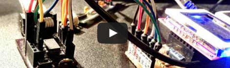
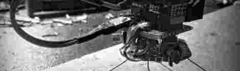
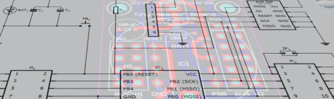
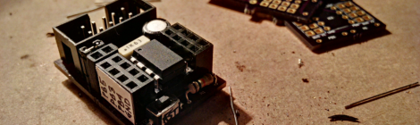
This is a oscilloscope-like circuit for the Tinusaur, it is not a real oscilloscope but could be used as a base for one. It is built on top of the Tinusaur board (Atmel AVR ATiny85) and Nokia 3310/5110 LCD (PCD8544 controller). There is also simple preamplifier for the electret microphone connected to the ADC of … Read more