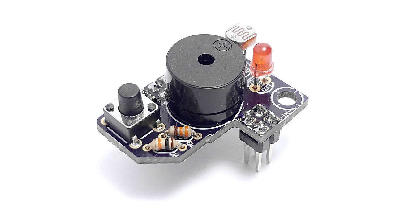
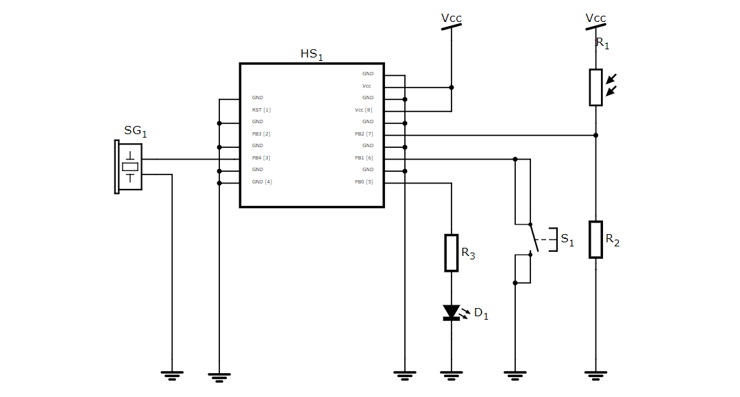
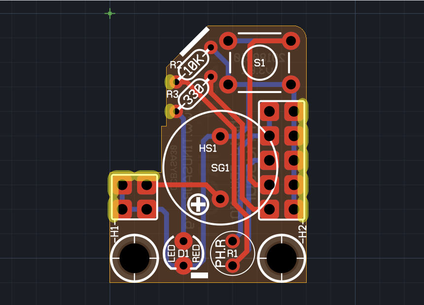
This is the Tinusaur Shield EDUx4IO. It is perfect for educational purposes.
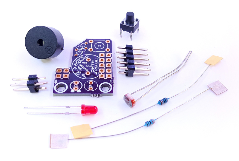
It consists of 4 essential components:
- Button – as digital input
- LED – as digital output or analog output
- Photoresistor – as analog input
- Buzzer – as digital output or analog output
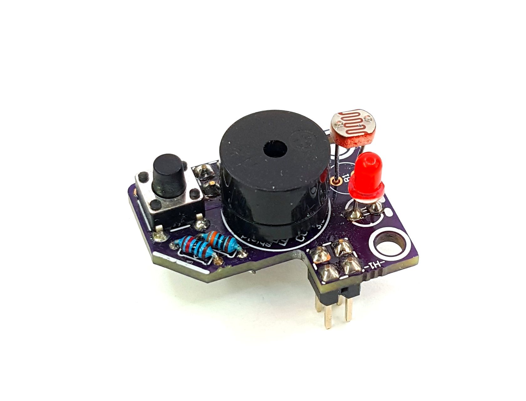
Or put in different perspective:
- Digital input – the button
- Digital output – the LED and the buzzer
- Analog input – the photoresistor
- Analog output – the LED and the buzzer
Here is the list of everything included with the Tinusaur Shield EDUx4IO:
| # | Name | Description |
| 1 | Shield, PCB | Shield EDUx4IO PCB |
| 2 | H1, Header | Header 2×4, Male (1) |
| 3 | H2, Header | Header 2×5, Male |
| 4 | LED1, LED | LED, 3mm, red |
| 5 | PHR1, Photoresistor | Photoresistor |
| 6 | R (LED1) | Resistor 330 ohm, Small, 1/8W, for LED1 (2) |
| 7 | R (PHR1) | Resistor 10K, Small, 1/8W, for PHR1 (2) |
| 8 | BUZ, Buzzer | Buzzer, passive |
| 9 | BUT, Button | Button, pushbutton, tactile. |
- (1) In some older models, the header is 2×4.
- (2) The resistor could be in different colors. Its value is marked with a color code – the color stripes on its body. Ref.: Wikipedia.org / Electronic color code – Resistor_color-coding
IMPORTANT: Please note that …
- In order to use the shield, you will need a Tinusaur Board to put it on.
- This is a kit, you have to assemble it yourself.
Guides

