New Product: Tinusaur Shield LEDx2

Tinusaur Shield LEDx2

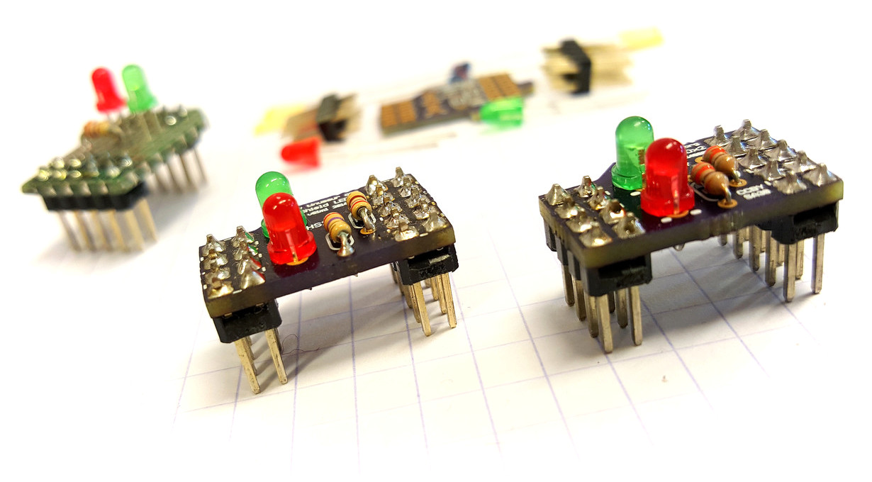
As we’ve mentioned earlier (What is happening with this project?) we were working on shield-like add-on board for the Tinusaur Board.

So here it is …

Tinusaur Shield LEDx2 Parts

It has only 2 LEDs and 2 resistors for each LED so no much to solder.

This shield aims at 2 things – making it easier to …

This shield has its own page at Products / Tinusaur Shield LEDx2.

UPDATED: DS1307 Library

The functions were moved to separate files in the DS1307tiny library.

The sample code in the ds1307tiny_test1 module looks cleaner now. The output should be something like this …

DS1307 Serial Real-Time Clock USITWIX ATtiny85

Note that one of the challenges working with a real-time clock the the DS1307 is to set it up with the correct time at the beginning.

  • One way is to do that programmatically – write a program for the microcontroller that will set the clock to specific date & time and run that program right at the specified in the code date & time.
  • Another way of doing taht is to use some sort of USB-to-I2C module and set the date & time from the computer. Such modules exist but they are kind of expensive for the simeple thing they do.
    Ref: http://www.ebay.com/sch/i.html?LH_BIN=1&_nkw=USB+to+I2C&_sop=15

References

Source code available at: https://bitbucket.org/tinusaur/ds1307tiny

More information about the library will be available at its own page: DS1307tiny


Working with DS1307 Real-time Clock and ATtiny85 using USITWIX Library

DS1307 Serial Real-Time Clock USITWIX Tinusaur.

Working with the DS1307 Serial Real-Time Clock using the USITWIX library for I2C / TWI on Atmel ATtiny85 / Tinusaur.

Let’s see how can we work with the DS1307 serial real-time clock using the USITWIX library for I2C / TWI on Atmel ATtiny85 / Tinusaur.

Bellow is the testing setup.

NOTE: We need the USB-to-Serial just for debugging – it isn’t essential part of the setup.

DS1307 Serial Real-Time Clock USITWIX Tinusaur.

There is no library yet to do that but with in the testing code there are few functions that could do the job.

Here is brief a description of the functions:

  • uint8_t ds1307_read_reg8(uint8_t reg_addr) – reads one byte of data from the specified register.
  • uint8_t ds1307_write_reg8(uint8_t reg_addr, uint8_t reg_data) – write one byte of data to the specified register.
  • uint8_t ds1307_init(void) – initializes the circuit by writing specific data into the registers.
  • uint8_t ds1307_setdatetime(uint16_t year, uint8_t month, uint8_t date, uint8_t weekday, uint8_t hour, uint8_t min, uint8_t sec) – sets date and time.
  • uint8_t ds1307_adjust(void) – this is helper function – it sets the date & time to a specific value – let’s not forget that a brand new circuit does not have correct date and time set.

DS1307 Serial Real-Time Clock ModuleThere are 2 additional functions that are used to convert data byte to and from BCD format.

  • static uint8_t bcd2bin (uint8_t val)
  • static uint8_t bin2bcd (uint8_t val)

This is direct link to the source code of the testing program:
https://bitbucket.org/tinusaur/ds1307tiny/src/default/ds1307tiny_test1/main.c

Source code available at: https://bitbucket.org/tinusaur/ds1307tiny

More information about the library will be available at its own page: DS1307tiny

Working with BMP180 Pressure Sensor and ATtiny85 using USITWIX Library

USITWIX – Using USI as TWI / I2C

In our previous post “USITWIX – Using UART as TWI / I2C” we looked at the USITWIX library that implements TWI / I2C communication between а  ATtiny85 micro-controller and peripherals. Let’s see now how we can use that library to work with the BOSCH BMP180 atmospheric pressure sensor and a ATtiny85/Tinusaur boards.

The BMP180tiny Library

So, we wrote a simple library (called it BMP180tiny) that uses USITWIX to read and write from/to BMP180 registers, retrieve the measurements, do some additional calculations and produce result suitable for use in an application.

Setup

Here’s the setup:

BMP180 with Tinusaur ATtiny85 USITWIX

NOTE: We need the USB-to-Serial just for debugging – it isn’t essential part of the setup.

Here is a short fragment of initialization code

uint8_t bmp180_result;
if ((bmp180_result = bmp180_init()) != BMP180_RESULT_SUCCESS)
{
return -1;
}

And here is now to use the functions …

// Read raw temperature
uint16_t temp_rawdata = bmp180_read_temp_raw();

uint16_t temp_10x = bmp180_read_temp10x();
// temp_10x holds the result dC, i.e. 123 means 12.3 Celsius

// Read raw pressure
int32_t pres_rawdata = bmp180_read_pres_raw();

// Read pressure
int32_t pres = bmp180_read_pres();
int16_t pres_hpa = pres / 100;
// pres_hpa holds the result in hPa (hectopascals)

// Read altitude
int32_t alt_x = bmp180_read_alt_x();
int16_t alt_dm = alt_x / 100;
// alt_dm holds the result in dm (decimeters)

The debugging output would look something like this …

t:raw=28622; t(dC)=253; p:raw/hi=5; p:raw/lo=4940; p(Pa)/hi=1; p(Pa)/lo=33948; p(hPa)=994; a/lo=24222; a(dm)=1552;
t:raw=28624; t(dC)=253; p:raw/hi=5; p:raw/lo=4964; p(Pa)/hi=1; p(Pa)/lo=33933; p(hPa)=994; a/lo=24307; a(dm)=1553;
t:raw=28623; t(dC)=253; p:raw/hi=5; p:raw/lo=4951; p(Pa)/hi=1; p(Pa)/lo=33939; p(hPa)=994; a/lo=22619; a(dm)=1536;
t:raw=28624; t(dC)=253; p:raw/hi=5; p:raw/lo=4942; p(Pa)/hi=1; p(Pa)/lo=33940; p(hPa)=994; a/lo=24560; a(dm)=1556;

NOTE: This is generated using OWOWOD library and hardware (not required by the library itself to work)

References

The source code is available at https://bitbucket.org/tinusaur/bmp180tiny.
— The library is in the “bmp180tiny” folder.
— A sample code could found in the “bmp180tiny_test1” folder.

The page about BMP180tiny and articles about BMP180tiny.

The page about USITWIX and articles about USITWIX.

New Library: USITWIX – Using USI as TWI / I2C

Attiny85 Tinusaur USI TWI I2C BMP180 Variometer

As we know, there’s no I²C on ATtiny85, not even the TWI (Two Wire Interface, which is basically I2C with a different name) that some other Atmel chips have, so I had to write my own that takes advantage on the built-in USI unit. This library is called USITWIX and will be presented in this blog post.

Of course, I used other people’s work write mine and they’re references in the source code.

The primary source is the Atmel application note AVR312: Using the USI module as a I2C slave that explains how to use the  built-in USI unit as I2C slave.

The source code is already available at https://bitbucket.org/tinusaur/usitwix.

Some important code fragments

Although the TWI and I2C is a synchronous communication protocol it still requires precise timing.

In the code there are few places where some fixed time intervals are specified and this is in the usitwim.h file:

#define T2_TWI 5 // >4,7us
#define T4_TWI 4 // >4,0us

These may need to be adjusted if the CPU runs at a frequency different than default 1 MHz.

Using the USITWIX library

Paragliding

The BMP180TINY is another library for working with the BOSCH BMP180 atmospheric pressure sensor.The source code is available at https://bitbucket.org/tinusaur/bmp180tiny along with some samples.

There is also a Variometer project that uses those libraries to produce audible measurements of the changes in the altitude by measuring the atmospheric pressure and taking into account the temperature. Such tools, or instruments, are often used by paragliders.

Video here:
https://www.youtube.com/watch?v=6JTnYuJGo4w

References

Here are some references to sources that I used while working on this project.

AVR312: Using the USI module as a I2C slave
http://www.atmel.com/Images/doc2560.pdf
C-code driver for TWI slave, with transmit and receive buffers; Compatible with I2C protocol; Interrupt driven, detection and transmission/reception; Wake up from all sleep mode, including Power Down.

TINY USI Interface in I2C mode and the AVR312 Appnote
http://www.aca-vogel.de/TINYUSII2C_AVR312/APN_TINYUSI_I2C.html
What’s wrong with the AVR Appnote?

ATTiny USI I2C Introduction – A powerful, fast, and convenient communication interface for your ATTiny projects!
http://www.instructables.com/id/ATTiny-USI-I2C-The-detailed-in-depth-and-infor/
I2C, it’s a standard that’s been around for around 20 years and has found uses in nearly every corner of the electronics universe. It’s an incredibly useful technology for us microcontroller hobbyists but can seem daunting for new users. This tutorial will solve that problem, first by reviewing what I2C is and how it works, then by going in-depth on how to implement I2C in Atmel’s ATTiny USI (Universal Serial Interface) hardware.

I2C Bus for ATtiny and ATmega
http://www.instructables.com/id/I2C_Bus_for_ATtiny_and_ATmega/
This two wire interface is formally known as the Inter-Integrated Circuit bus, or just the I2C bus and was invented by NXP when it was still Philips Semiconductors. If you’re reading this Instructable then you’ve probably heard of the I2C bus and may even have used it on a PIC or other microcontroller. While conceptually very simple, and supported by hardware resources on the AVRs, software drivers are still necessary to use the I2C bus. Atmel provides Application Notes (see the Resources later in this Instructable), but these are incomplete and don’t show any examples beyond communicating with another AVR device.

ATtiny85 and ESP8266 – do you really need that?

Tinusaur ATtiny85 ESP6288 Shield

Yes, why not. And here is what I did …

(this will be series of posts about what I did with ATtiny85/Tinusaur and ESP8266 WiFi module)

First, what could be accomplished with such limited device as ATtiny85? It has 8 pins, 2 of which are for the power (Vcc and GND), one for the RESET (pin 1 – PB5), another one potentially for the OWOWOD debugging (pin 2 – PB3) through serial line, so there are 4 pins left: PB0, PB1, PB2, PB4.

ATtiny85 pinout

ESP8266 module uses UART to communicate so it would require at least 2 pins to work – URxD and UTxD.

There is also CH_PD pin that controls the chip and could power it down.

ESP8266 module pinout

At first it may look that this takes another 3 pins out but not really.

If we use the CH_PD to disconnect the ESP8266 module we can use the same pins for other purposes like connecting additional I²C devices to the micro-controller. This is what I did.

What are the challenges?

1) There’s no UART on ATtiny85 so I had to write my own that takes advantage on the built-in USI unit. The library is called USIUARTX and will be presented in another blog post. The source code will be uploaded at https://bitbucket.org/tinusaur/ very soon.

2) There’s no I2C on ATtiny85, not even the TWI (Two Wire Interface, basically I2C) that some other Atmel chis have, so I had to write my own that takes advantage on the built-in USI unit. The library is called USITWIX and will be presented in another blog post. The source code is already available at https://bitbucket.org/tinusaur/usitwix. The BMP180TINY library (Source code at https://bitbucket.org/tinusaur/bmp180tiny) uses it to communicate with an BMP180 pressure sensor.

That’s it for now.

My next post will be about the above mentioned libraries.

The OWOWOD Library

OWOWOD is One Wire / One Way Output for Debugging library. It allows you to output text from the Tinusaur (ATtiny85 microcontroller or other similar), though USB-to-Serial or TTL converter (based on PL2303, CH340G or similar) and to the computer screen using COM port monitoring tool.

Why one would need something like that?

It would’ve been nice if it was possible to write something li this …

debugging_print("working, x=%i", x);

… and see the output on a computer. Great for debugging and other things.

Unfortunately ,there is no easy way of doing that – in fact not possible with the standard tools used to work with the ATtiny85. The problem is this: (1) those micro-controllers have too few I/O ports; and (2) most of the programmers (ex.: USBasp) do not offer that kind of communication between the micro-controller and the computer, i.e. there is no 2-way communication.

USB to Serial TTL

There are some solution and the OWOWOD library is just one of them. It uses an additional hardware component – USB-to-Serial converter also known as USB TTL Converter. They are very inexpensive, easy to find and work with.

The OWOWOD Library could do that.

Tinusaur connected to USB-to-Serial PL2303 using OWOWOD

For this to work we need …

  • Micro-controller
  • USB-to-Serial converter
  • Computer

The Library works like this …

  • When you use a library function like owowod_print_char(‘U’) it will start sending sending the bits of the ‘U’ byte (hex: 0x55, bin: 01010101) in series, i.e. one bit after another, through one of the microcontroller pins – for instance PB3.
  • At the other end of the wire there is USB-to-Serial converter that will take the individual 01010101 bits and re-compose them back into one byte as 0x55.
  • Then the USB-to-Serial converter will send that ‘U’ byte (0x55) to the computer USB port.
  • The computer sees the USB-to-Serial as a Serial COM Port port, so it reads that ‘U’ byte.
  • Using another program on the computer we get that ‘U’ byte and show it on the screen.

It works similarly for whole strings and other data.

Let’s take a look at some usage examples:

#include <stdlib.h>
#include <avr/io.h>
#define OWOWOD_PORT PB3
#include "../owowod/owowod.h"
int main(void) {
    owowod_init();
    owowod_print_char('U');
    owowod_print_string("Hello!\r\n");
    owowod_print_numdec(1);
    owowod_print_numdecp(2);
    owowod_print_numdecu(123);
    owowod_print_numdecup(456);
    return 0;
}

Always initialize with owowod_init() function.

You can print char, string but also decimal signed and unsigned integer numbers.

The decimal numbers are 16-bit integers.

The owowod_print_numdecp() and owowod_print_numdecup() functions print left padded numbers – that means there will be some spaces on the left as if the numbers are right aligned. Like this …

    12
   345
 67890
    -2
   -34
-56789

Because this would be used for debugging in most of the cases there are some helpful definitions for that purpose in the “debugging.h” file.

Here is an example of how to use it …

#define F_CPU 1000000UL
#include <stdint.h>
#include <avr/io.h>
#define OWOWOD_PORT PB3
#include "../owowod/owowod.h"
#include "../owowod/debugging.h"
int main(void) {
    DEBUGGING_INIT();
    DEBUGGING_NUMDEC(-123);
    DEBUGGING_NUMDECP(-4567);
    DEBUGGING_NUMDECU(123);
    DEBUGGING_NUMDECUP(4567);
    DEBUGGING_STRING("Hello!");
    DEBUGGING_STRINGLN("Hi!");
    DEBUGGING_VAR("X", 1);
    DEBUGGING_VARU("Y", 23);
    DEBUGGING_ERROR(4, "Connect");
    return 0;
}

DEBUGGING_STRINGLN adds CRLF new line at the end.

DEBUGGING_VAR and DEBUGGING_VARU print variable name and then the value.

DEBUGGING_ERROR prints the error code then the message.

hercules setup serial

To see the results we need a program that will run on a computer and show on the screen the information that comes through the serial port. There are many programs that could do that. One particularly simple to use is the Hercules Setup utility by HW group – it is just one EXE file that you run – that’s it.

The OWOWOD has its own page, it is at:
/projects/owowod/

This library was developed with and tested on the following microcontrollers: ATtiny85, ATtiny45, ATtiny25 but should also work on other tinyAVR chips.

The library was tested to work with following USB-to-Serial converters: PL2303, CH340G.

Source code is available at https://bitbucket.org/tinusaur/owowod.

References

There are many project in the Internet that solve the same or similar problems and this article http://www.ernstc.dk/arduino/tinycom.html that points to some of them:

On eBay: USB to Serial TTL converter – to transfer the debugging output from the ATtiny micro-controller to the computer.

Here are links to some of the posts related to this library:

Printing Decimal Numbers on SSD1306 OLED Display Using the SSD1306xLED Library

Tinusaur SSD1306XLED SSD1306 OLED Llibary

UPDATE: Please, check the most recent post about this library at /tag/ssd1306xled

After playing for awhile with that SSD1306 OLED display I decided to add few more things to the SSD1306xLED library and the ability to print numbers seamed to be an important one.

Tinusaur SSD1306xLED ATtiny85 SSD1306 OLDEThere is already a function in the library that outputs strings so I needed only the conversion from int to a decimal string. So I used another function usint2decascii that I previously wrote for another project OWOWOD which code, in turn, I borrowed from a third project LCDDDD – an LCD Direct Drawing Driver for PCD8544 based displays such as Nokia 3310 LCD. The weird LCDDDD name comes from the fact that it outputs the data directly to the LCD instead of storing it into a buffer first and then periodically outputting it to the LCD – this is unlike most of the popular LCD drivers.

Here is the main function definition …

uint8_t usint2decascii(uint16_t num, char* buffer)

The function requires a small buffer to store the result. Since the largest number is 65535 – that is 0xFFFF in hex, 5+1 bytes are needed for that buffer.

For convenience, there are 2 functions for direct printing of numbers. Below is their implementation – it’s very simple:

#define USINT2DECASCII_MAX_DIGITS 5

char ssd1306_numdec_buffer[USINT2DECASCII_MAX_DIGITS + 1];

void ssd1306_numdec_font6x8(uint16_t num) {
  ssd1306_numdec_buffer[USINT2DECASCII_MAX_DIGITS] = '&#092;&#048;';
  uint8_t digits = usint2decascii(num, ssd1306_numdec_buffer);
  ssd1306_string_font6x8(ssd1306_numdec_buffer + digits);
}

void ssd1306_numdecp_font6x8(uint16_t num) {
  ssd1306_numdec_buffer[USINT2DECASCII_MAX_DIGITS] = '&#092;&#048;';
  usint2decascii(num, ssd1306_numdec_buffer);
  ssd1306_string_font6x8(ssd1306_numdec_buffer);
}

The ssd1306_numdec_font6x8 only prints the number while ssd1306_numdecp_font6x8 prints numbers the same way but right-aligned and 5-digit padded.

Printing numbers is as simple as this …

  ssd1306_setpos(20, 4);
  ssd1306_numdecp_font6x8(12345);

Here is a little more complicated example …

ssd1306_setpos(40, 3);
ssd1306_string_font6x8("a=");
ssd1306_numdecp_font6x8(0xFA32); // dec: 64050
ssd1306_setpos(40, 4);
ssd1306_string_font6x8("b=");
ssd1306_numdecp_font6x8(0x05CD); // dec: 1485

ssd1306xled sample screen

It prints “a=”, “b=” and then their values. Both numbers are right-aligned and left-padded with up to 4 spaces.

The latest test program in SSD1306xLED includes examples of how to use the ssd1306_numdec_font6x8 and the ssd1306_numdecp_font6x8 functions.

The SSD1306xLED library is at SSD1306xLED page.

The source code of the SSD1306xLED is available at https://bitbucket.org/tinusaur/ssd1306xled

The source code of the TinyAVRLib is available at https://bitbucket.org/tinusaur/tinyavrlib

Tutorial 003: Making Sounds with Buzzer

Electromagnetic Buzzer

So far we’ve used a LED as output to produce light of different colors and intensity (Tutorial 001 and Tutorial 002) but we haven’t generated any sound yet.

In fact, that isn’t very difficult to do.

We will use a buzzer for output.

According to Wikipedia … the buzzer or beeper is an audio signaling device, which may be mechanical, electromechanical, or piezoelectric. Typical uses of buzzers and beepers include alarm devices, timers, and confirmation of user input such as a mouse click or keystroke.

Tinusaur Buzzer

We will use an electromechanical buzzer. When voltage is applied to it its membrane moves up (or down, depending on the particular device), and respectively when there is no voltage the membrane goes back to its normal position. Applying constantly changing voltage will generate audio waves perceived by us as a sound.

Let’s connect the buzzer to the PB2 of the ATtiny85 on the Tinusaur board.

The program should look very much like the one for blinking LED except that the delay between switching the port should be very short.

In the example below we have a delay 500 and since we’re using the _delay_us() function that means the delay is 500 uS (microseconds). That means the period of the signal will be 2 x 500 uS = 1000 uS (or 0.0001 sec.) and then the frequency is 1 / 0.0001 S = 10000. That means the sound will have a frequency of 10 KHz.

Here is the source code:

#include <stdint.h>
#include <avr/io.h>
#include <util/delay.h>
#define BUZZER_PORT     PB2     // Buzzer I/O Port
#define BUZZER_DELAY    500     // Delay for each tick
int main(void)
{
    DDRB |= (1 << BUZZER_PORT); // Set port as output
    while (1) {
        PORTB |= (1 << BUZZER_PORT);
        _delay_us(BUZZER_DELAY);
        PORTB &= ~(1 << BUZZER_PORT);
        _delay_us(BUZZER_DELAY);
    }
    return (0);
}

Full source code with more comments and the other necessary files such as Makefile is available at https://bitbucket.org/tinusaur/tutorials/src/default/tut003_buzzer/

Build the program:

$ make

Upload the code to the controller:

$ avrdude -c usbasp -p t85 -U flash:w:"main.hex":a

The buzzer should start making sounds immediately.

Let’s do some more experiments.

Let’s make the delay between the buzzer ticks change over time and see what sound it will produce.

This time instead of _delay_us() we will use the _delay_loop_2() function. According to the _delay_loop_2(int) documentation it produces 4 empty CPU cycles per iteration – in other words with parameter 100 it will produce a delay of 400 CPU cycles. That tells us that the maximum is 65536 x 4 = 262252 cycles. That, at 1MHz CPU clock, is approximately 262 mS (milliseconds) maximum delay, … or about 3.8 Hz minimum frequency – perfect for our experiments.

Below is the source code:

#include <stdint.h>
#include <avr/io.h>
#include <util/delay.h>
#define BUZZER_PORT     PB2     // Buzzer I/O Port
#define BUZZER_DELAY    200     // Delay for each tick
int main(void)
{
    DDRB |= (1 << BUZZER_PORT); // Set port as output
    int delay = 0;
    while (1) {
        if (delay < 1) delay = BUZZER_DELAY;
        PORTB |= (1 << BUZZER_PORT);
        _delay_loop_2(delay);
        PORTB &= ~(1 << BUZZER_PORT);
        _delay_loop_2(delay);
        delay--;
    }
    return (0);
}

After building and uploading this should start making sounds like a car alarm.

With similar techniques, a lot more complex sounds could be generated.

This post will eventually become Tutorial 003.

The Tinusaur Boards are Back in Stock

Tinusaur Starter KitFinally!

All the parts were received from our suppliers – The Tinusaur Board and The Tinusaur Starter are back in stock at our online store at Storenvy.

We don’t have the resource to supply more that couple of hundred boards at once so if they sold out like the last time please be patient – we will replenish our online store as soon as we can.

The prices, as it is our promise, have not changed since the first batch of boards we shipped. We don’t make profit either. So if you really want to help us keep this project going please consider making a small donation via PayPal.