UPDATE 2022: The MAX7219LED8x8 library, now renamed to MAX7219tiny has now a new home at tinusaur.com/libraries/max7219tiny/. Check also this MAX7219 & ATtiny85 tutorial to learn how the library works.
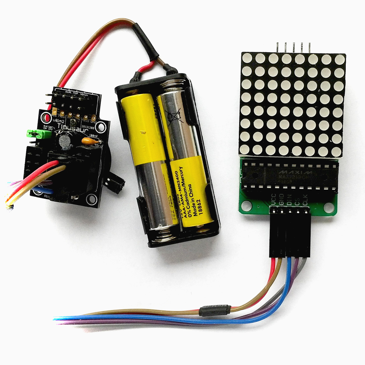
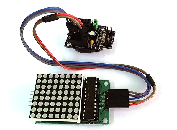
MAX7219Led8x8 is a C library for working with the MAX7219 display driver to control 8×8 LED matrix. It is intended to be used with the Tinusaur board but should also work with any other board based on ATtiny85 or similar microcontroller.
MAX7219
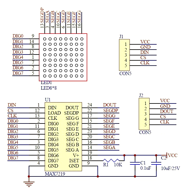
The MAX7219 is manufactured by Maxim Integrated is compact, serial input/output common-cathode display driver that could interface microcontrollers to 64 individual LEDs, 7-segment numeric LED displays of up to 8 digits, bar-graph displays, etc. Included on-chip are a BCD code-B decoder, multiplex scan circuitry, segment and digit drivers, and an 8×8 static RAM that stores each digit. Only one external resistor is required to set the segment current for all LEDs.
To put that in simpler words – with the MAX7219 driver it is possible to control 8×8 LED matrix using just 2 wires serial interface – one for the sync clock and one for the data. There is another wire that could be used to enable/disable the communication with the chip. The maximum frequency for the serial interface is 10MHz.
LED Matrix 8×8
The LED matrix 8×8 is connected almost diretcly to the MAX7219 driver – only few external components are required.

Library
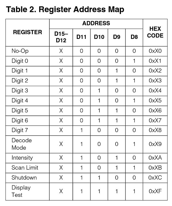
Working with MAX7219 is very simple – turning on and off individual LEDs is done by sending 2-bytes command to the driver containing the row and the byte which bits define which LED value to set.
There are also few other command that are needed during the initialization process.
The library supports short buffer – only 8 bytes in size – to keep the values before sending them to the driver.
MAX7219LED8x8 is written in plain C and does not require any additional libraries to function except those that come with the WinAVR SDK.
The library consists of 2 file:
- max7219led8x8.h
- max7219led8x8.c
Source Code
MAX7219_DIN, MAX7219_CS, MAX7219_CLK define the microcontroller pins that will be used to connect to the driver.
max7219led8x8.h
/*
 * MAX7219Led8x8 - Tinusaur MAX7219 Library for LED 8x8 Matrix
 *
 * @file: max7219led8x8.h
 * @created: 2014-07-12
 * @author: Neven Boyanov
 *
 * Source code available at: https://bitbucket.org/tinusaur/max7219led8x8
 *
 */

#ifndef MAX7219LED8X8_H
#define MAX7219LED8X8_H

// ---------------------    // Vcc, Pin 1 on LED8x8 Board
// ---------------------    // GND, Pin 2 on LED8x8 Board
#ifndef MAX7219_DIN
#define MAX7219_DIN     PB0 // DI,  Pin 3 on LED8x8 Board
#endif
#ifndef MAX7219_CS
#define MAX7219_CS      PB1 // CS,  Pin 4 on LED8x8 Board
#endif
#ifndef MAX7219_CLK
#define MAX7219_CLK     PB2 // CLK, Pin 5 on LED8x8 Board
#endif

void MAX7219_byte(uint8_t data);
void MAX7219_word(uint8_t address,uint8_t dat);
void MAX7219_init(void);
void MAX7219_row(uint8_t address,uint8_t dat);
void MAX7219_buffer_out(void);
void MAX7219_buffer_set(uint8_t x, uint8_t y);
void MAX7219_buffer_clr(uint8_t x, uint8_t y);

#endif
max7219led8x8.c
/*
 * MAX7219Led8x8 - Tinusaur MAX7219 Library for LED 8x8 Matrix
 *
 * @file: max7219led8x8.h
 * @created: 2014-07-12
 * @author: Neven Boyanov
 *
 * Source code available at: https://bitbucket.org/tinusaur/max7219led8x8
 *
 */

#include <stdlib.h>
#include <avr/io.h>
#include <util/delay.h>

#include "max7219led8x8.h"

void MAX7219_byte(uint8_t data)
{
    PORTB &= ~(1 << MAX7219_CS);    // Set to LOW
    for(uint8_t i = 8; i >= 1; i--)
    {
        PORTB &= ~(1 << MAX7219_CLK);   // Set to LOW
        if ((data & 0x80) != 0)         // Mask the MSB of the data
            PORTB |= (1 << MAX7219_DIN);    // Set to HIGH
        else
            PORTB &= ~(1 << MAX7219_DIN);   // Set to LOW
        data = data<<1;
        PORTB |= (1 << MAX7219_CLK);        // Set to HIGH
    }
}

void MAX7219_word(uint8_t address, uint8_t data)
{
    PORTB &= ~(1 << MAX7219_CS);    // Set to LOW
    MAX7219_byte(address);          //
    MAX7219_byte(data);             //
    PORTB |= (1 << MAX7219_CS);     // Set to HIGH
}

void MAX7219_init(void)
{
    DDRB |= (1 << MAX7219_CLK); // Set port as output
    DDRB |= (1 << MAX7219_CS);  // Set port as output
    DDRB |= (1 << MAX7219_DIN); // Set port as output
    _delay_ms(50);  // TODO: Q: Is this necessary?
    MAX7219_word(0x09, 0x00);   // Decode: BCD
    MAX7219_word(0x0a, 0x03);   // Brightness
    MAX7219_word(0x0b, 0x07);   //
    MAX7219_word(0x0c, 0x01);   //
    MAX7219_word(0x0f, 0x00);   //
}

void MAX7219_row(uint8_t address, uint8_t data) {
    if (address >= 1 && address <= 8) MAX7219_word(address, data);
}

uint8_t MAX7219_buffer[8] = { 0x00, 0x00, 0x00, 0x00, 0x00, 0x00, 0x00, 0x00 };

void MAX7219_buffer_out(void) {
    // Output the buffer
    for (uint8_t row = 1; row <= 8; row++)
        MAX7219_row(row, MAX7219_buffer[row - 1]);
}

void MAX7219_buffer_set(uint8_t x, uint8_t y) {
    uint8_t sx = 7 - (x & 0b0111);
    uint8_t sy = (y & 0b0111);
    MAX7219_buffer[sy] |= (1 << sx);
}

void MAX7219_buffer_clr(uint8_t x, uint8_t y) {
    uint8_t sx = 7 - (x & 0b0111);
    uint8_t sy = (y & 0b0111);
    MAX7219_buffer[sy] &= ~(1 << sx);
}
Please note that the source code above may improve or change so check the latest version at the source code repository on this address https://bitbucket.org/tinusaur/max7219led8x8.
Usage
This is a fragment of code using this library …
    MAX7219_init();
    MAX7219_buffer_set(2, 3); // Set pixel
    MAX7219_buffer_clr(4, 5); // Clear pixel
    MAX7219_buffer_out(); // Output the buffer
This will do the folowing:
- initialize the driver
- set a pixel – turn a LED on
- clear a pixel – turn a LED off
- send buffer to driver
Very simple, isn’t it?
Testing Program
The following is a very simple program that uses the library. It will turn on all the LEDs – one by one, then it will turn them off the same way.
/*
 * MAX7219Led8x8 - Tinusaur MAX7219 Library for LED 8x8 Matrix
 *
 * @file: main.c
 * @created: 2014-07-12
 * @author: Neven Boyanov
 *
 * Source code available at: https://bitbucket.org/tinusaur/max7219led8x8
 *
 */

#define F_CPU 1000000UL

#include <stdlib.h>
#include <avr/io.h>
#include <util/delay.h>

// ---------------------    // Vcc, Pin 1 on LED8x8 Board
// ---------------------    // GND, Pin 2 on LED8x8 Board
#define MAX7219_DIN     PB0 // DI,  Pin 3 on LED8x8 Board
#define MAX7219_CS      PB1 // CS,  Pin 4 on LED8x8 Board
#define MAX7219_CLK     PB2 // CLK, Pin 5 on LED8x8 Board

#include "../max7219led8x8/max7219led8x8.h"

int main(void) {

    // ---- Initialization ----
    MAX7219_init();

    // ---- Main Loop ----
    while (1) {
        for (uint8_t y = 0; y <= 7; y++) {
            for (uint8_t x = 0; x <= 7; x++) {
                MAX7219_buffer_out();   // Output the buffer
                MAX7219_buffer_set(x, y);   // Set pixel
                _delay_ms(10);
            }
        }
        for (uint8_t y = 0; y <= 7; y++) {
            for (uint8_t x = 0; x <= 7; x++) {
                MAX7219_buffer_out();   // Output the buffer
                MAX7219_buffer_clr(x, y);   // Clear pixel
                _delay_ms(10);
            }
        }
    }

    return 0;
}
The program does this in an infinite loop.
External Resources
The source code of the MAX7219LED8x8 library is available at https://bitbucket.org/tinusaur/max7219led8x8
MAX7219 specification and datasheet:


What is the purpose of the J2 connector with the Data Out pin? Can these matrixes be daisy-chained to form larger displays? If so, how do you address each module? This project is impressive, but Life on a 32×32 display run by an ATtiny85 would be even more compelling.
Yes, you can connect more LED modules in series, although I haven’t done it.
The other thing is that the LED modules that I’m using will not fit together as 2×2 … you’ll need custom built board for that with MAX7219 controller for each 8×8 matrix.