This is the Tinusaur User Guide. It contains general information about the Tinusaur Project, the Tinusaur Board, the components that are used as well as some other useful information.
The Tinusaur Project
Briefly, the Tinusaur is a minimal micro-controller hardware configuration based on Atmel AVR ATtiny family of products and more specifically those with DIP-8 case such as ATtiny25/ATtiny45/ATtiny85, ATtiny13 as well as their variations.
The goal of the Tinusaur project is to have a simple, cheap and accessible quick-start platform for everyone interested in learning and creating things.
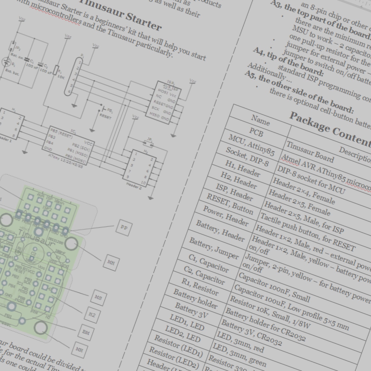
Tinusaur Starter
The Tinusaur Starter is a beginners’ kit that will help you start with microcontrollers and the Tinusaur particularly.
There are 4 areas that a Tinusaur board could be divided to: A1, A2, A3, A4. That is applicable for the actual Tinusaur main board as well as any shield boards one could produce.
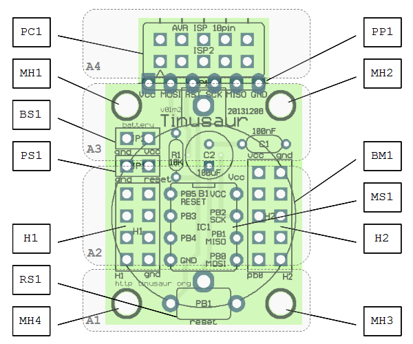
A1, the bottom part of the board:
-
this is the area where the RESET button is placed on the main board.
-
for a shield board that area could be used to put some components and produce a simple circuit.
A2, the mid of the board – heads:
-
there are 2 header – one 2×4 and another one 2×5, they are different for a reason.
-
on the main board, between the headers, is placed the MCU.
-
on a shield board, between the headers, could placed an 8-pin chip or other components.
A3, the top part of the board:
-
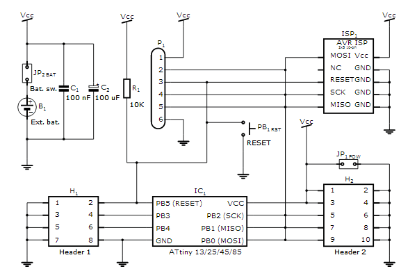
there are the minimum required components for the MSU to work – 2 capacitors for the power source and one pull-up resistor for the RESET.
-
jumper for external power – red.
-
jumper to switch on/off battery – yellow.
A4, tip of the board:
-
standard ISP programming connector.
Additionally …
A5, the other side of the board:
-
there is optional cell-button battery mount.
Package Contents
| Name | Description |
| PCB | Tinusaur Board |
| MCU, Attiny85 | Atmel AVR ATtiny85 microcontroller |
| Socket, DIP-8 | DIP-8 socket for MCU |
| H1, Header | Header 2×4, Female |
| H2, Header | Header 2×5, Female |
| ISP, Header | Header 2×5, Male, for ISP |
| RESET, Button | Tactile push button, for RESET |
| Power, Header | Header 1×2, Male, red – external power |
| Battery, Header | Header 1×2, Male, yellow – battery power on/off |
| Battery, Jumper | Jumper, 2-pin, yellow – for battery power on/off |
| C1, Capacitor | Capacitor 100nF, Small |
| C2, Capacitor | Capacitor 100uF, Low profile 5×5 mm |
| R1, Resistor | Resistor 10K, Small, 1/8W |
| Battery holder | Battery holder for CR2032 |
| Battery 3V | Battery 3V, CR2032 |
| LED1, LED | LED, 3mm, red |
| LED2, LED | LED, 3mm, green |
| Resistor (LED1) | Resistor 330 ohm, Small, 1/8W, for LED |
| Resistor (LED2) | Resistor 330 ohm, Small, 1/8W, for LED |
| Header (LED1) | Header 1×2, Male, for LED |
| Header (LED2) | Header 1×2, Male, for LED |
| ISP Programmer | USB ASP, 10-pin connector, with cable |
An older version of this document could be also downloaded as PDF file at this link: Tinusaur Starter User Guide