This is the Tinusaur Board Assembling Guide. It contains general information about the Tinusaur Project, the Tinusaur Board, the components that are used and how to solder them on the board, as well as some other useful information.
The Tinusaur Project
The Tinusaur is a minimal microcontroller hardware configuration based on Atmel AVR ATtiny family of products and more specifically those with DIP-8 case such as ATtiny85.
The goal of the Tinusaur project is to have a simple, inexpensive and accessible quick-start platform for everyone interested in learning microcontrollers and creating things.
Tinusaur Board
The Tinusaur Board is what the Tinusaur project is built around. It is rather simple PCB with a dozen components on it.
The board is easy to assemble and does not require very special skills or instruments.
IMPORTANT: If you are uncertain about anything please consult with our website, community or someone more knowledgeable in the subject.
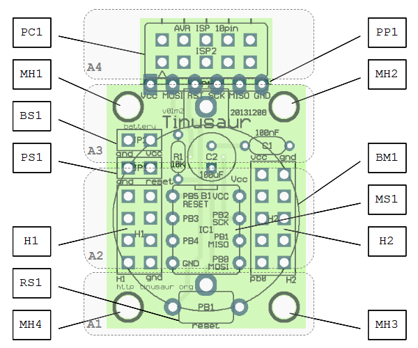
There are 4 areas that the Tinusaur board could be divided to: A1, A2, A3, A4.
Assembling
Here is the recommended order of soldering the parts:
- MCU socket. Note: do not insert the chip yet.
- Capacitors C1, C2 and resistor R1.
- Headers H1, H2.
- External power header – red.
Battery on/off header – yellow. - ISP header.
- Battery holder.
- RESET button.
The battery holder and the battery are optional but if you decided to put them on make sure you solder the battery holder before the RESET button.
IMPORTANT:
External power header (JP1, red, the one closer to the 8-pin header H1) is to connect external power. DO NOT put a jumper there – that could damage the board.
Battery On/Of header (JP2, yellow, the one closer to the mount hole) is to connect/disconnect battery to/from the board. DO NOT have this on while the board is connected to the programmer or external power source – there is no circuit to protect the battery from overcharging.
If you’re not going to use an external power source or the battery on the board don’t put any jumper on at all.
Board Components
| Name | Description |
| PCB | Tinusaur Board |
| MCU, Attiny85 | Atmel AVR ATtiny85 microcontroller |
| Socket, DIP-8 | DIP-8 socket for MCU |
| H1, Header | Header 2×4, Female |
| H2, Header | Header 2×5, Female |
| ISP, Header | Header 2×5, Male, for ISP |
| RESET, Button | Tactile push button, for RESET |
| Power, Header | Header 1×2, Male, red – external power |
| Battery, Header | Header 1×2, Male, yellow – battery power on/off |
| Battery, Jumper | Jumper, 2-pin, yellow – for battery power on/off |
| C1, Capacitor | Capacitor 100nF, Small |
| C2, Capacitor | Capacitor 100uF, Low profile 5×5 mm |
| R1, Resistor | Resistor 10K, Small, 1/8W |
| Battery holder | Battery holder for CR2032 |
| Battery 3V | Battery 3V, CR2032 |
Note (about external power source): If you’re going to use external power source (JP1, red in color, the one close to the 8-pin header H1) make sure you connect the negative pole (-) to the outer pin of the header and positive (+) to the inner one.
Note (about battery placement): If you’re going to use the battery in the holder make sure you insert it correctly – that is to have the negative (-) downwards (facing the holder) and the positive (+) (the side with the text markings) upwards.
An older version of this document could be also downloaded as PDF file at this link: Tinusaur Board Assembling Guide