This is simple tutorial that shows how to connect a LED to the ATtiny85 based Tinusaur board and write a program that makes the LED to fade in and out using PWM (pulse-width-modulation) technique.
Note: The code in this tutorial does not use the built-in PWM capabilities of the ATtiny microcontrollers, instead it uses direct bit manipulation since this un easier way to understand how it works. Another tutorial should cover the PWM functionality that is built into the microcontroller.
Since the Tinusaur board is a very standard ATtiny breakout board this could be applied to almost any other board that has ATtiny microcontroller on it.
The code was tested to work with ATtiny13, ATtiny25, ATtiny45 and ATtiny85 but will probably work with other ATtiny microcontrollers as well.
Prerequisites
We assume that:
- The Tinusaur board was successfully assembled and proven to work.
- The USBasp ISP programmer is connected to the computer and to the Tinusaur board and is properly working.
- The development environment (like WinAVR) was properly setup.
Note: It is not the subject of this tutorial to show how to assemble the board or setup the ISP programmer and the development environment.
Hardware
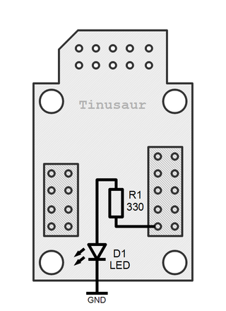
The LED D1 should be connected to the PB0 of the microcontroller which is pin 5 on the chip. This should be done through the resistor R1 and to the GND.
The LED, marked as D1, is just a standard 5mm or 3mm light emitting diode.
The resistor, marked as R1, should be 270 ohm to 330 ohm.
Software
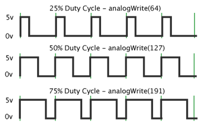
The program is very simple. It turns on and off the LED very fast – more that 100 times per second. When it is off for longer period of time (compared to the period of time when it is on) the intensity of the LED will be lower. Similarly, when it is on for longer period of time (compared to the period of time when it is off) its intensity will be higher.
The ratio between the on and off time is also called duty cycle.
Here is the code:
#include <avr/io.h>
#include <util/delay.h>
#define LED1_PORT PB0
int main(void) {
  // Set the LED port number as output.
  DDRB |= (1 << LED1_PORT);
  uint8_t fade_out = 0;
#define BIAS_MAX 600
#define BIAS_MIN 1
  uint16_t bias = BIAS_MIN;
  // Begin an infinite loop. This is how most programs work.
  while (1) {
    // Set the LED port bit to "1" - LED will be turned on.
    PORTB |= (1 << LED1_PORT);
    // Wait a little. The delay function simply does N-number of "empty" loops.
    _delay_loop_2(bias);
    // Set the LED port bit to "0" - LED will be turned off.
    PORTB &= ~(1 << LED1_PORT);
    // Wait a little.
    _delay_loop_2(BIAS_MAX - bias);
    if (fade_out == 0) {
      bias++;
      if (bias >= BIAS_MAX - 1) fade_out = 1;
    }
    else {
      bias--;
      if (bias <= BIAS_MIN) fade_out = 0;
    }
    // Do that again ...
  }
  // Return the mandatory for the "main" function value.
  return (0);
}
The first meaningful line is this:
#define LED1_PORT PB0This defines the port that will be used for the LED.
Then we have to setup that port as an output. This is done with the following line of code:
DDRB |= (1 << LED1_PORT);The DDRB is the MCU register to specify the data direction for port B. What the code does is this:
- shifts a “1” on left, N-times depending on the LED1_PORT value.
- does bitwise “OR” with the value in the port register DDRB.
This ways if the LED1_PORT was set to “5” – the “5-th” bit of DDRB will be set to “1”.
Setting the value of the bit to “0”, if and where necessary, could be done with this:
DDRB &= ~(1 << LED1_PORT);What this line of code does is this:
- shifts the “1” on left, N-times depending on the LED1_PORT value; and …
- does XOR (inversion of the bits); and …
- does bitwise “AND” with the value in the port register DDRB.
The most important fragment of the code is this:
    // Set the LED port bit to "1" - LED will be turned on.
    PORTB |= (1 << LED1_PORT);
    // Wait a little. The delay function simply does N-number of "empty" loops.
    _delay_loop_2(bias);
    // Set the LED port bit to "0" - LED will be turned off.
    PORTB &= ~(1 << LED1_PORT);
    // Wait a little.
    _delay_loop_2(BIAS_MAX - bias);
    if (fade_out == 0) {
      bias++;
      if (bias >= BIAS_MAX - 1) fade_out = 1;
    }
    else {
      bias--;
      if (bias <= BIAS_MIN) fade_out = 0;
    }
This looks like a Blinking LED program except that the delay between the on and off cycles is changing over time by the bias variable. Its value starts from BIAS_MIN, goes up to BIAS_MAX and then back down to BIAS_MIN.
That changes the duty cycle of the PWN from about 5% to about 95% and then back to 5% in result of which the LED will fade in and out.
That’s it.
WinAVR
If you’re using WinAVR you need to go to the project folder and do this:
$ makeThen program it using AVRDUDE:
$ avrdude -c usbasp -p t85 -B 0.5 -U flash:w:"main.hex":aThis should put the binary code up on the microcontroller and the LED should start fading in and out immediately.
Source code
Source code is available on Bitbucket at this address: https://bitbucket.org/tinusaur/tutorials/src/default/tut002_fading_led_x1/
How to make this works for 2 or more leds with independent port?
With this configuration you can connect up to 5 LEDs using PB0, PB1, PB2, PB3, PB4.
What do you want those LEDs do, fading in and out in sync or something else?
I may try to put some code here of you tell me what you need.
Hello!
I know this post is 9 years old and there’s almost no chance anyone will respond, but I hope maybe there will be someone to offer a helping hand.
How can this code to be changed so that the led lights up once ( fade in > fade out > pause 10 seconds, and again ) at a repeated 10 second interval and not continuously?
Thank you very much!
All the best!
Mihai!