Yes, why not. And here is what I did …
(this will be series of posts about what I did with ATtiny85/Tinusaur and ESP8266 WiFi module)
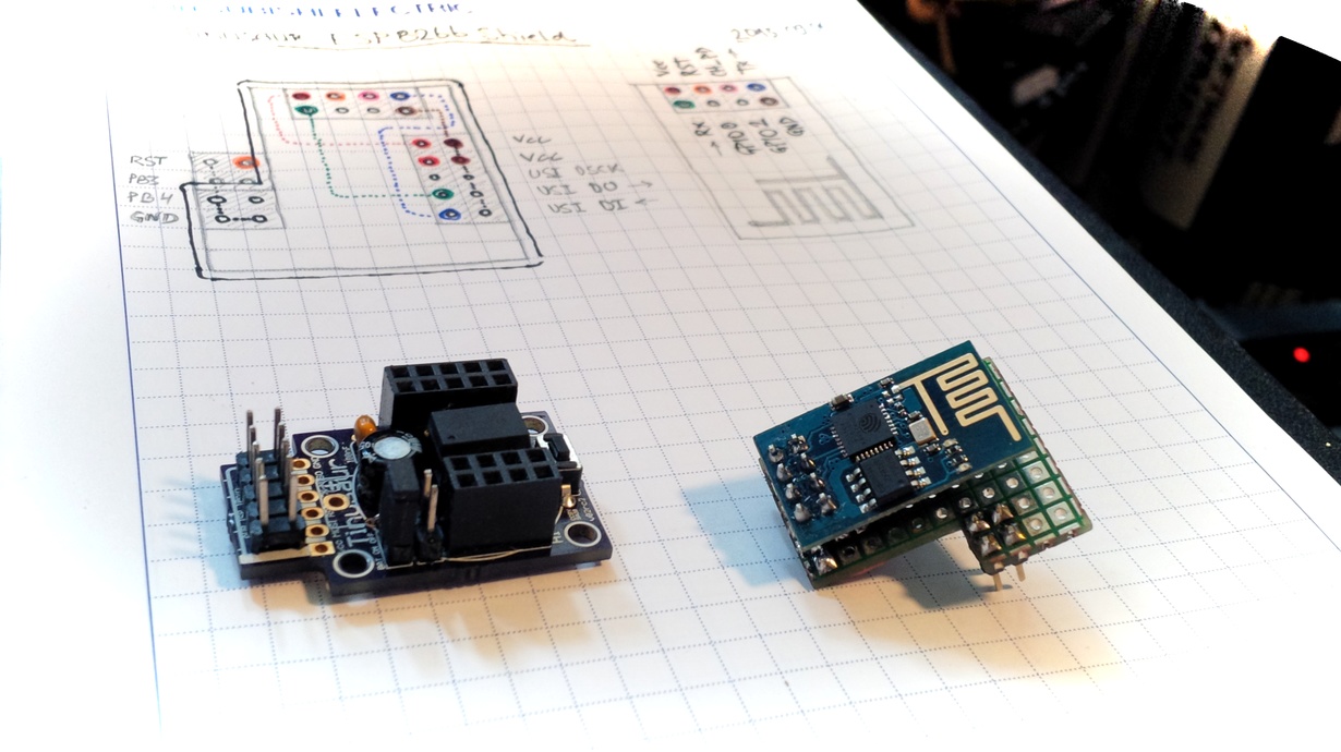
First, what could be accomplished with such limited device as ATtiny85? It has 8 pins, 2 of which are for the power (Vcc and GND), one for the RESET (pin 1 – PB5), another one potentially for the OWOWOD debugging (pin 2 – PB3) through serial line, so there are 4 pins left: PB0, PB1, PB2, PB4.

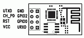
ESP8266 module uses UART to communicate so it would require at least 2 pins to work – URxD and UTxD.
There is also CH_PD pin that controls the chip and could power it down.
At first it may look that this takes another 3 pins out but not really.
If we use the CH_PD to disconnect the ESP8266 module we can use the same pins for other purposes like connecting additional I²C devices to the micro-controller. This is what I did.
What are the challenges?
1) There’s no UART on ATtiny85 so I had to write my own that takes advantage on the built-in USI unit. The library is called USIUARTX and will be presented in another blog post. The source code will be uploaded at https://bitbucket.org/tinusaur/ very soon.
2) There’s no I2C on ATtiny85, not even the TWI (Two Wire Interface, basically I2C) that some other Atmel chis have, so I had to write my own that takes advantage on the built-in USI unit. The library is called USITWIX and will be presented in another blog post. The source code is already available at https://bitbucket.org/tinusaur/usitwix. The BMP180TINY library (Source code at https://bitbucket.org/tinusaur/bmp180tiny) uses it to communicate with an BMP180 pressure sensor.
That’s it for now.
My next post will be about the above mentioned libraries.